Hi there,
The purpose of this little instrument is to test the behavior of PSU's under dymanic conditions.
It is basically a power switch controlled by an oscillator. It requires a power load that is going to be chopped, and possibly another one for the preloading of the PSU UT.
These functions could have been included, but then the level of complexity would be on a totally different scale (and the volume too, due to heatsinks).
This box is just a bare switch and its driver, which is OK by me, since I already have adjustable loads.
For many years, the method I used for this kind of test was to pick a suitable MOSFet, and connect it to the load and function generator with alligator clips.
For a one off it's perfectly OK, but if you need this on a regular basis, something more deterministic and reliable is welcome, which why I took the leap, at last.
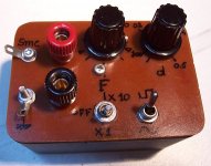
No rocket science involved, just an oscillator adjustable in frequency (10Hz~1Khz) and duty cycle (50%~10%).
A synchronization output is included, as is a slew control switch.
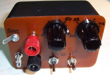
The design is very (very!) compact, battery operated and built in an insulating case, meaning completely floating and free of any potential, something always useful.
No power LED is included: since the current consumption is well below 1mA, any low-current LED would at least double or treble the battery drain.
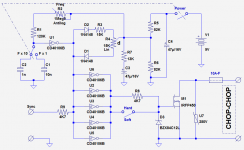
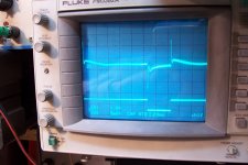
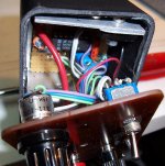
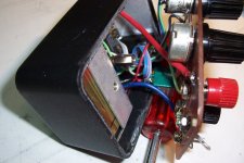
Here is the circuit, some pics of my prototype, waveforms showing the effect of the soft/sharp switch, and an actual measurement on a supply
The purpose of this little instrument is to test the behavior of PSU's under dymanic conditions.
It is basically a power switch controlled by an oscillator. It requires a power load that is going to be chopped, and possibly another one for the preloading of the PSU UT.
These functions could have been included, but then the level of complexity would be on a totally different scale (and the volume too, due to heatsinks).
This box is just a bare switch and its driver, which is OK by me, since I already have adjustable loads.
For many years, the method I used for this kind of test was to pick a suitable MOSFet, and connect it to the load and function generator with alligator clips.
For a one off it's perfectly OK, but if you need this on a regular basis, something more deterministic and reliable is welcome, which why I took the leap, at last.
No rocket science involved, just an oscillator adjustable in frequency (10Hz~1Khz) and duty cycle (50%~10%).
A synchronization output is included, as is a slew control switch.
The design is very (very!) compact, battery operated and built in an insulating case, meaning completely floating and free of any potential, something always useful.
No power LED is included: since the current consumption is well below 1mA, any low-current LED would at least double or treble the battery drain.
Here is the circuit, some pics of my prototype, waveforms showing the effect of the soft/sharp switch, and an actual measurement on a supply
Attachments
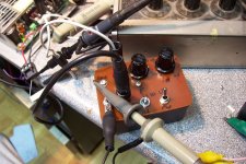
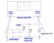
See below a typical test set-up.I want to build this. Please explain how I should connect to a power supply and scope.
Suppose you want to test a 5V supply for a 1 amp step: you make R1 4.7 ohm (of a sufficient power).
If you want to test the behaviour for a step of 1 --> 2A, you add R2, also 4.7 ohm.
The BOM depends on your needs and what you have available.Also BOM.
Since I wanted to be able to test HV supplies, I have used a 500V MOSFET, but if you work at low voltages only, you can use a lower voltage part, with the advantage of a higher maximum current and a lower Rdson.
The fuse and varistor have to be dimensioned according to the MOS capabilities.
You can alter the values to suit the contents of your junk-box: the pots I have used are 15K and 1.5Meg, which is a bit unusual, but you could use 22K and 2.2Meg, and increase R1 R5 R6 R7 + decrease C1 C2 in the same proportion.
The circuit is very tolerant and flexible
It can test basically any power supply, and the limits are set only by the MOSFET you have chosen (and the power loads you have available).What type of power supplies can it test, and is there a limit to the input voltage and current?
If you have contradictory needs, like being able to test 800V low current supplies and 3.3V 50A ones, you can even use two different MOSFETs in the same box, with a common control and two outputs.
My choice is a tradeoff that will cover 99% of my needs
Attachments
How is it Used
Elvee,
How does one use your chopper?
In the pics that you posted how would someone diagnose their
power supply using the chopper?
What do we want to see?
What don't we want to see?
Are there any examples of it?
or
Would you please post some examples of it.
I don't know, that is why I ask.
Other DIYers might not know either
and it probably would help them also.
And for those that do know thank you
for your patience.
I do not need to answer that myself, the subject is very well covered: just a little googling:Elvee,
How does one use your chopper?
In the pics that you posted how would someone diagnose their
power supply using the chopper?
What do we want to see?
What don't we want to see?
Are there any examples of it?
or
Would you please post some examples of it.
I don't know, that is why I ask.
Other DIYers might not know either
and it probably would help them also.
And for those that do know thank you
for your patience.
Ridley Engineering | - Step Load Testing
http://cds.linear.com/docs/en/application-note/an104f.pdf
http://pdfserv.maximintegrated.com/en/an/AN3453.pdf
http://www.ti.com/lit/an/snoa507/snoa507.pdf
http://cp.literature.agilent.com/litweb/pdf/5952-4190.pdf
http://powerelectronics.com/site-fi...onics.com/images/OptimalTransientResponse.pdf
Etc...
Thank you ELVEE.
I found the following :
It might be equivalent to teaching Deutsch fuer Auslander
by giving them a book, I mean who needs a teacher.
Then the gut Deutscher und Deutscherin will laugh
while the person who studied so diligently mis
pronounces all the words wrong gender and
even worse--syntax errors.
I mean even if you learn Deutsch with a teacher,
professor, and travel there, one still won't have
an understanding of why people laugh when
someone would say, " Ich habe Pimple auf
meine gesicht." I have a pimple on my face,
is no big deal right? We all get them.
Just like telling you "I am a sweet roll". That
wasn't me, that was John F. Kennedy saying that.
I think if I had a better understanding of the actual process,
also known as the "big picture" it might have helped me out some.
Because I don't have that back ground that is why I asked my
questions.
From the articles and tech notes to which you provided links
I perused every page,graph, and figure and no where did it show me
what is Good, what is NOT Good, except for the parts that stood out
which I recognized were bad?
I'm aware of Phase Margin because I've read a few comments from
the good folks here at DIY. I still don't know which angles are good
or desirable and which are not.
Since you wouldn't answer my questions above would you at least
share with me what the original Jensen Paper Capacitors were
designed for?
If someone else would care to take the time to explain this thread to me,
I would appreciate it. I am very interested in learning more about it because
it seems it would help me analyze power supplies in ways I haven't imagined.
Please know I am just trying to learn all this stuff for the first time.
I'm not a young gun any longer, I'm in the latter 1/2 of middle age.
Which translated means I"m just trying to learn what most of you have forgotten.
I struggle to learn this stuff. On my little bench just when I get all set
up to work or do something, my little 23 month old daughter needs
attention or runs in or something dangerous.
It is almost like clockwork really, and it makes having that time to
experiment or run some tests very difficult, even going through
some laboratory project books....last thing I want her to do is
come in and place a coat hanger across an open box, primaries, or
aligator clips test set up.
I found the following :
- A bunch of Testing Setups, with plots/graphs showing ringing.
- Discussion of Phase Margin.
- PARD, P-P, RMS
- Mucho Testa Equipmento
It might be equivalent to teaching Deutsch fuer Auslander
by giving them a book, I mean who needs a teacher.
Then the gut Deutscher und Deutscherin will laugh
while the person who studied so diligently mis
pronounces all the words wrong gender and
even worse--syntax errors.
I mean even if you learn Deutsch with a teacher,
professor, and travel there, one still won't have
an understanding of why people laugh when
someone would say, " Ich habe Pimple auf
meine gesicht." I have a pimple on my face,
is no big deal right? We all get them.
Just like telling you "I am a sweet roll". That
wasn't me, that was John F. Kennedy saying that.
I think if I had a better understanding of the actual process,
also known as the "big picture" it might have helped me out some.
Because I don't have that back ground that is why I asked my
questions.
From the articles and tech notes to which you provided links
I perused every page,graph, and figure and no where did it show me
what is Good, what is NOT Good, except for the parts that stood out
which I recognized were bad?
I'm aware of Phase Margin because I've read a few comments from
the good folks here at DIY. I still don't know which angles are good
or desirable and which are not.
Since you wouldn't answer my questions above would you at least
share with me what the original Jensen Paper Capacitors were
designed for?
If someone else would care to take the time to explain this thread to me,
I would appreciate it. I am very interested in learning more about it because
it seems it would help me analyze power supplies in ways I haven't imagined.
Please know I am just trying to learn all this stuff for the first time.
I'm not a young gun any longer, I'm in the latter 1/2 of middle age.
Which translated means I"m just trying to learn what most of you have forgotten.
I struggle to learn this stuff. On my little bench just when I get all set
up to work or do something, my little 23 month old daughter needs
attention or runs in or something dangerous.
It is almost like clockwork really, and it makes having that time to
experiment or run some tests very difficult, even going through
some laboratory project books....last thing I want her to do is
come in and place a coat hanger across an open box, primaries, or
aligator clips test set up.
Here are two examples of where I have difficulties trying to understand
what various examples are trying to impart or impress upon the reader.
In this case the reader is me. Call me nieve, ignorant, dumkopf, or what have you
but for some reason (I've been through the related text a few
times also) I am still missing the intent and what the author wanted
me to learn from it.
I'll include a third example that is kind of hard to follow and I'll also
include that as well. It will follow the initial two if I can put it in here
in the limited time available, other wise it will be in the post following this.
Questionable Learning Example 1:

Questionable Learning Example 2:

what various examples are trying to impart or impress upon the reader.
In this case the reader is me. Call me nieve, ignorant, dumkopf, or what have you
but for some reason (I've been through the related text a few
times also) I am still missing the intent and what the author wanted
me to learn from it.
I'll include a third example that is kind of hard to follow and I'll also
include that as well. It will follow the initial two if I can put it in here
in the limited time available, other wise it will be in the post following this.
Questionable Learning Example 1:
Questionable Learning Example 2:

Basically, the step-load test is a stress test: you abuse the S.U.T. in a violent manner (you give it a good kick), and you examine how it behaves.
An ideal supply would stay rock-solid under any circumstance (=flat line on the scope), but real supplies are far from that ideal.
The response gives you insights about the output capacitor/filter, the open-loop gain and most importantly, the behavior of the regulation loop.
For example, a relatively low frequency undershoot, overshoot or even sustained ringing indicates an improper frequency compensation of the said loop.
A higher frequency ringing might indicate an insufficient damping of the last filter section of an SMPS.
In general, the more the response departs from the flat line, the worst is the supply.
This is a summary: covering all aspects would mean a course of hundreds of pages, and this is not the purpose of a thread on a forum.
The information is abundantly available in books and on the web, you need to absorb it at your own rhythm. If you start from scratch, it may take weeks or months before you get a sufficient expertise to be fluent in the subject, but that is journey you have to make by yourself. Use your brain and your common sense, ask yourself questions, try to answer them. It is like any learning process.
If you stumble on a particular difficulty, you can always post a question, but I cannot engage in general course.
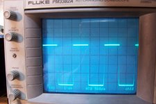
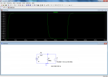
Here are a few example of things you can observe with this kind of stimulus.
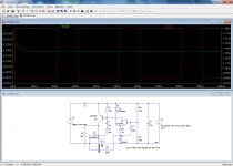
First pic shows a simple, discrete LDO with its normal compensation scheme: the output current is switched between 0.9A and 1.8A.
The green trace shows that the OP voltage is slightly affected: there is a ~static part of small amplitude (difference between the two levels) related to the output resistance and ultimately the open loop gain, and a dynamic part near the transitions reflecting the behavior of the OP capacitor and the servo loop.
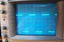
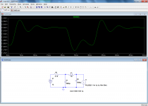
Now, imagine that in a moment of madness, I apply a compensation 10 times heavier than what is necessary (C1 R1).
The quasi-static aspect is unchanged, logically, but the dynamic behavior is completely ruined: when the load is released, there is a huge overshoot. Not good.
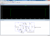
Another example: a simple 12V supply.
Now, imagine I want to improve the noise/ripple rejection with an additional post-filter.
The rejection might be improved, but the dynamic behavior is seriously degraded, with a ringing apparent.
This would show as a peak in the impedance vs. frequency plot.
In short, it is a powerful diagnostic tool capable of showing many different types of misbehavior at a glance
First pic shows a simple, discrete LDO with its normal compensation scheme: the output current is switched between 0.9A and 1.8A.
The green trace shows that the OP voltage is slightly affected: there is a ~static part of small amplitude (difference between the two levels) related to the output resistance and ultimately the open loop gain, and a dynamic part near the transitions reflecting the behavior of the OP capacitor and the servo loop.
Now, imagine that in a moment of madness, I apply a compensation 10 times heavier than what is necessary (C1 R1).
The quasi-static aspect is unchanged, logically, but the dynamic behavior is completely ruined: when the load is released, there is a huge overshoot. Not good.
Another example: a simple 12V supply.
Now, imagine I want to improve the noise/ripple rejection with an additional post-filter.
The rejection might be improved, but the dynamic behavior is seriously degraded, with a ringing apparent.
This would show as a peak in the impedance vs. frequency plot.
In short, it is a powerful diagnostic tool capable of showing many different types of misbehavior at a glance
Attachments
Hello,
Very good job your Chop-chop box Elvee !
We seem to have same concern with at this time.
I've built these days, two different tools also in order to test the lab PSU i currently designed (EPSUX3v2).
One of these is based on the AN104 from LinearTech that you have linked.
It work fine (As all Jim Williams design) !
So, just a link to the related post where is it describe. if someone are interested...
Regards.
Frex
No, it is so simple that I didn't bother to make a "working" .asc, the schematic is purely graphic and won't work in sim.Hi Elvee. Nice tool. Do you by chance have a .asc for the Chop Chop box?
That's extremely simple though, and you could have it working in less than 2 minutes.
D3 protects the gate of the MOSbut I am stuck on some of the subtleties (e.g. the purpose of D3, U7, C4)
U7 protects the MOS against overvoltages (if the load is inductive for example)
C4 is simply the supply bypass cap.
In a sim, all of these components can be omitted
ok no problem. I was just looking to play around with it on the off-chance you had made it. At least I was right in my thinking re U7 and D3 (but lacking confidence) - C4 was a "duh" moment.
I'm working on a somewhat simpler device for the same purpose - with a bit less adjustability. It is a circuit suggested by Mark Johnson which uses an LMC555 and MCP1407 (plus suitable MOSFET). It has the ability to adjust frequency but the duty cycle is fixed at 50%. Your added features such as hard/soft and Fx10 are nice touches.
I'm still trying to understand how your duty cycle adjustment works.
- Status
- This old topic is closed. If you want to reopen this topic, contact a moderator using the "Report Post" button.
- Home
- Design & Build
- Equipment & Tools
- Chop-chop box