Had one of these on the shelf for awhile now.
We all know the story line...went to use it and
not working.
My plan is to get it working first
then upgrade some parts, i.e., 741 opamp.
I'm learning too and this little unit is probably
not as demanding or as finicky as the HP339A
that has been giving me fits.
I originally picked it up because it does a variety of signal generating
and can perform sweep functions and provide carrier functions.
Haven't opened it up yet but guessing it won't be the PITA to
work on that the HP339a is.
I found the operators manual and the service manual online.
Kind of fuzzy hard to read but should be workable. I've read through
the dead thread about this unit and that should be a good reference to
start from. I would have posted there, but I want to start from dead
and then upgrade.
I'll post some oscillator pics first
to show what the minimal output
looks like.
Now I've got to find them.
to show what the minimal output
looks like.
Now I've got to find them.
Oh the un-Joy of using windows 8.1.
What ever you do, don't get anything with Microsoft 8.1.
It is the worst operating system I've ever used. Microsoft
trys to force you into some unknown MS world, most of the
old apps that I have don't work with it. You are forced to
use some klugy OS that wants to be some type phone on
your computer.
That aside, the bottom is what I've been able to upload.
Based on what I have found, I think there was a batch
of defective boards from Leader. These appear to be
defects on the output section where there are heat
and output problems. Unless this burned up so badly
that the traces and solder mask had to be rubbed out
for the board to function again.
Not a very good repair in my opinion. Once the carbon
is on a board it should, all of it needs to be removed other
wise it keeps getting worse over time.
Then, the first series of tests were in spec except the final
test on TP-3, which was -10.03 vs. -10.00 +- 1%.
Close enough not be the problem.
I then checked TP2, which was 44.2V P or 88.4 P-P.
Seems high but the doco I have doesn't show data for that
point.
Another problem seems to have the 220pf polystryene cap
right next to the hottest part of the main board. This is C207
which was underlined in my version of the service manual.
Also, since i've not used these things before, I guess they work
the following way:
A 1k sine wave is output, then if triangle is selected it places
a small triangle wave over the AC wave?
For some reason I was thinking the output would be one Large triangle wave
at a frequency of 1kHz.


And of course the scope pic at 44Vac peak I forgot to take.
In the process of cleaning up the board. The burned side of the board
is runny, looks like a layer of something is all over it running from back
to front.
I'm thinking I need to removed all these components then sand off all the
burned carbon, then cut a small portion of bread board without traces and
glue it to the old board....
Once dry, then reinstall new components or old components that still
work if I can't find replacements.
What ever you do, don't get anything with Microsoft 8.1.
It is the worst operating system I've ever used. Microsoft
trys to force you into some unknown MS world, most of the
old apps that I have don't work with it. You are forced to
use some klugy OS that wants to be some type phone on
your computer.
That aside, the bottom is what I've been able to upload.
Based on what I have found, I think there was a batch
of defective boards from Leader. These appear to be
defects on the output section where there are heat
and output problems. Unless this burned up so badly
that the traces and solder mask had to be rubbed out
for the board to function again.
Not a very good repair in my opinion. Once the carbon
is on a board it should, all of it needs to be removed other
wise it keeps getting worse over time.
Then, the first series of tests were in spec except the final
test on TP-3, which was -10.03 vs. -10.00 +- 1%.
Close enough not be the problem.
I then checked TP2, which was 44.2V P or 88.4 P-P.
Seems high but the doco I have doesn't show data for that
point.
Another problem seems to have the 220pf polystryene cap
right next to the hottest part of the main board. This is C207
which was underlined in my version of the service manual.
Also, since i've not used these things before, I guess they work
the following way:
A 1k sine wave is output, then if triangle is selected it places
a small triangle wave over the AC wave?
For some reason I was thinking the output would be one Large triangle wave
at a frequency of 1kHz.
And of course the scope pic at 44Vac peak I forgot to take.
In the process of cleaning up the board. The burned side of the board
is runny, looks like a layer of something is all over it running from back
to front.
I'm thinking I need to removed all these components then sand off all the
burned carbon, then cut a small portion of bread board without traces and
glue it to the old board....
Once dry, then reinstall new components or old components that still
work if I can't find replacements.
Last edited:
C207 is on that list non polystyrene (maybe a good polyproplene cap.
How would a Mica do in this position?
Tricky I think will be the encapsulated ICs
Q212 NPN 2SC1907
Q217 PNP 2SA571
Then the others which may be just fine:
Q211 PNP 2SA711
Q213 NPN 2SC97A
Q215 NPN 2SC1907
Q216 PNP 2SA711
On the solder side of the board, the Buss 1/10 fuse.
That is a start any way. Wondering what the root cause
that keeps frying the board.
Got it working again.
First I noticed a coating of goo on the solder side of the board.
Cleaned it up with isopropyl alcohol on Qtips and poly wipes.
Also cleaned up the burned area on the top of the board.
Didn't have the replacement fuse so had to make do with what
I had. Soldered leads onto a regular fuse, placed it in heat shrink
to keep it from shorting out. Heat shrink is longer than the fuse
to prevent shorting. Soldered it in to see where we were with the
unit.
Plugged it in and turned it on to see where we were with the
unit. It powers up and I have output on the front panel.
I took some pics which I'll post when I can.
Output is fine and was adjusted to 20v P-P.
However, it clips the lower part of the waves
with the attenuator buttons are pushed.
It looks like it would if you were using diode clippers
on the bottom have of all waves, sine, triangle, square...
Here are the pics of the "non-output" before fixed.
No attenuation. The only thing I think was going out
was a low level signal on a carrier, though I didn't
have carrier selected.
This is the sine wave problem:

Triangle wave problem:

Square wave problem:

No attenuation. The only thing I think was going out
was a low level signal on a carrier, though I didn't
have carrier selected.
This is the sine wave problem:
Triangle wave problem:
Square wave problem:
This is the temporary fix I did
to the board so that I could see
if there were any other problems.
I want to see if the thing will even
work.
This is a 1/10A fust that was removed
I didn't have a mini one to reinstall but
I did have some AGC 1/10A fuses.
Here's the board:

After that just checked the output per the manual:

Then I checked the various attenuation levels.
Here is the output with 10dB attenuation selected:

Nuts. It looks like a diode is clipping off the bottom half of
the signal, not good. More to check.
Here is the out with 40dB attenuation selected:

Same problem with the 20dB attenuation switch also.
Will do some further checking on schematic and some switch
cleaning when I get the chance.
to the board so that I could see
if there were any other problems.
I want to see if the thing will even
work.
This is a 1/10A fust that was removed
I didn't have a mini one to reinstall but
I did have some AGC 1/10A fuses.
Here's the board:
After that just checked the output per the manual:
Then I checked the various attenuation levels.
Here is the output with 10dB attenuation selected:
Nuts. It looks like a diode is clipping off the bottom half of
the signal, not good. More to check.
Here is the out with 40dB attenuation selected:
Same problem with the 20dB attenuation switch also.
Will do some further checking on schematic and some switch
cleaning when I get the chance.
Sync,
Here are links to the manuals. Make sure you read the operator's manual and make sure you have AM modulation off and the Symmetry is set correctly before you chase your tail.
Operator: http://eeshop.unl.edu/pdf/LFG1300S.pdf
Service: http://exodus.poly.edu/~kurt/manuals/manuals/Other/LEADER LFG 1300S Service.pdf
Dave
Ski,
Thanks for the heads up. Was going through the service manual.
from the part of the Operators Manual I can see now what I need
to set to.
The output control pot on the main board was set to max output,
about 23 Vac. I had backed that down to 20 v P-P.
Now I see that it should be 7 V rms.
Then, I bet (as I'm a betting man) the attenuation settings
will fall in line.
Hopefully no tail chasing. I never done that.
Cheers,
I'm working my way through the calibration procedure,
and I'm unsure of calibrating the Functions.
section3.5 (page3-3)
I've gone through it but not much really happens.
On the scope, I just adjusted a nice round corner on the sine wave,
between flat and pointy. None of the pots did much even on the
analyzer--barely a movement.
Triangular wave, Square wave, offset no problems.
Section 3.6 (page 3-5) AM Modulation is a different story,
as I've never done AM modulation or carriers before.
Uncertain after connect the audio generator to MOD IN connector...
"...and set the frequency to 1kHz, output level for 1Vp-p."
I set this on the oscillator output, 1kHz and output for 1V.
This was way too high for the 1V p-p on the scope, so I
put the scope on the oscillator and set it for 1Vp-p, then
reconnected as per the calibration procedure.
Neither way I tried, could I adjust the the scope or
adjust VR207 to look like that of Figure 3-1 (page 3-5).
I was able to to center a waveform and was able to set
A and B heights, but the problem was there was a flat
spot in the middle of the band and my sine wave pos
and neg were 180 degrees apart. That is the peaks
and valleys weren't aligned as shown in Figure 3-1.
If anyone who's performed this before can give me
some pointers I would appreciate it.
Cheers.
Then I back the oscillator voltage down so the scope shows
AM Update
Made it past the the section 3-5 and 3-6.
You just have to fool with it a bit and
the manual is incorrect in some parts.
Encountered some other issues...low level
oscillation, where you set the frequency dial
to .002 the scope shows the output
rising and falling slowly. Maybe
it is the master oscillator residual
or something.
Also difficult to dial in the dials frequency settings.
I'm guessing that R142, R143, R144 have drifted enough
that I can't get the range spot on:
.2 = 217 Hz
2 = 2.020 kHz.
Then
1 = 997 to 1.004 to 1.014 Hz on the freq counter.
Distortion on this seems to be so high that trying to use the
HP339a to measure it on the 0 dB Distortion Range leaves
the needle at 0dBV or full-range.
Brought out the QA400 to have a look see and it could
use that to dial it in. I could use that to find the lowest
distortion for 2 Hz to 20kHz. It's not a bad tool that
QA400. but it leaves you longing for more.
I just don't have the $$$$ for a larger spectrum analyzer.
Such is life.
One remaining problem is the section 6-3-4 the sweep generator
in the manual and Figure 6-2. shows the wave form rise at 20mS.
I can only get 11mS rise from it. I've adjusted the fall to 5mS.
The manual says 20mS, however the service manual says less than
or equal to 20mS. I'm not convinced they meant 11mS and that is
not adjustable.
One function that should have been explained earlier and not
burried in the manual is the DC offest control. I if you use
any attenuation of the output, you should check it on a scope
and adjust the DC offset so your wave won't clip. In my case
its the bottom half of the wave.
Now, that gets me to wondering how to mod this thing so that
with the DC offset knob set to zero, the wave is balanced, not
one side clipped. Perhaps measureing it putting
a resistor in series to "balance" the wave.
I might as well try pulling the 741 amps and replacing with
something better. Not sure how to measure or determine which
opamp to use....ops134, lt1468, LME47910....There are three
socketed in the center, don't know if better to use different
amps or use three the same as Leader did.
Working my way through it little bit by little bit as time permits.
I'll include scands when I can.
Help Board Fuse location
Can anyone check
OR
Does anyone know the exact location
of the fuse on the boards output.
From what I can tell it should be
something like between C207 & close
end of J16. Installed with a manually
cut trace?
I should get it right, just checking
as I don't want more burned out boards.
Cheers,
Can anyone check
OR
Does anyone know the exact location
of the fuse on the boards output.
From what I can tell it should be
something like between C207 & close
end of J16. Installed with a manually
cut trace?
I should get it right, just checking
as I don't want more burned out boards.
Cheers,
Update
LEADER LFG-1300S WORKING AGAIN
Got the function generator working again.
Oscillator and functions are right as spec'd level
which is a major improvement as it didn't work.
Lowest distortion I got on it was at -56.5dB with the
HP339a that is finally working again (thank
Mr. Richard N. Marsh for ending my misery).
A Few Minor Issues
There are a few minor issues with Leader LFG-1300s
that I think will lower distortion and help it's functionality....
1. Low level oscillation 20 Hz and below.
2. HF distortion seen on the scope, general thickening
of the sine wave.
3. All of the main board tuning pots are at the start
or ends of the rotation which has lower frequencies
and high frequencies.
Have not replaced any of the electrolytic's yet
as I wanted the unit working before I go farther.
One or two of them are just starting to increase
in value and ESR of some might be starting to rise.
741 OpAmp Swap & Distortion Measurements
I've tried swapping out the three 741 opamps with
others but in each case distortion and functionality
got worse. I didn't make any other changes.
Recall the baseline 741 opamp distortion -56.5 dB.
The opamps that were swapped in along with their distortion
measurements (if functioning) were the following:
LT1468 non-functioning
LME47910 -32dB
OPA134 -37.2 dB
In some instances I did try to dial in the frequencies
adjusting pots and test...but was still worse off.
So this tells me that just blindly subbing opamps isn't
going to do it, at least in my case. I didn't see any other
posts or information posted.
I'll post some pics of what I've done so far when I get the chance.
ASSISTANCE IS REQUESTED
This will be the point where I really need some assistance because
I don't have any formal background education or training in electronics.
Everything I've done up to this point has been self taught, school of hard
knocks, or some good folks helped me out a bit and showed me a thing
or two.
I got very good at trouble shooting, rebuilding, modifying tube amps
for musicians and some nice tube hi-fi stereo amplifiers.
Learning About Solid State
I am just learning about solid state electronics and all they have
to offer and the endless number of parts, chips, circuits, etc
that seem to always change and stopped being made, etc, etc.
The most help I've ever received is from you folks here at the
DIYAudio community. Y'all have been great, supportive,
and have enabled me to learn and grow.
I don't know enough about circuit design to know how to
modify the circuits in this function generator to get it to
work better and to use better components more modern
op amps, transistors etc.
Please know that I'm trying to learn what most of you have forgotten or
has become so second nature to you that you take it for
granted that I should be able to do it on my own.
It will take me way too long to do that. Yes I have pretty good
textbooks too. But some of it you read and go oh...but never get
a good feel for it or good understanding of it.
Now, I need some guidance as to how to get this thing
working...and upgrading it if you don't mind sharing your
knowledge with me.
Please know it is not just me but I'm sure other people
reading would be interested as well.
How to Proceed: Leader LFG-1300s
I think this Leader LFG-1300s is pretty good, has good functionality
a variety of circuits in it etc. I think my mechanical skills are solid,
my circuit knowledge is growing and this Leader has a lot of interesting
stuff for learning.
So, now that I've gotten this thing working and tried some simple
op amp swaps that didn't work so well, what do I need to know
going forward and how does one proceed?
You thoughts, knowledge and guidance will be appreciated.
Thank you in advance,
Pic's at 11pm (or when the lab develops them
Last edited:
Sync,
On vacation...but I have this model. I'll check some sine wave output scope shots when I get home. Remember, function generators do not have very low distortion sine waves.
Dave
On vacation...but I have this model. I'll check some sine wave output scope shots when I get home. Remember, function generators do not have very low distortion sine waves.
Dave
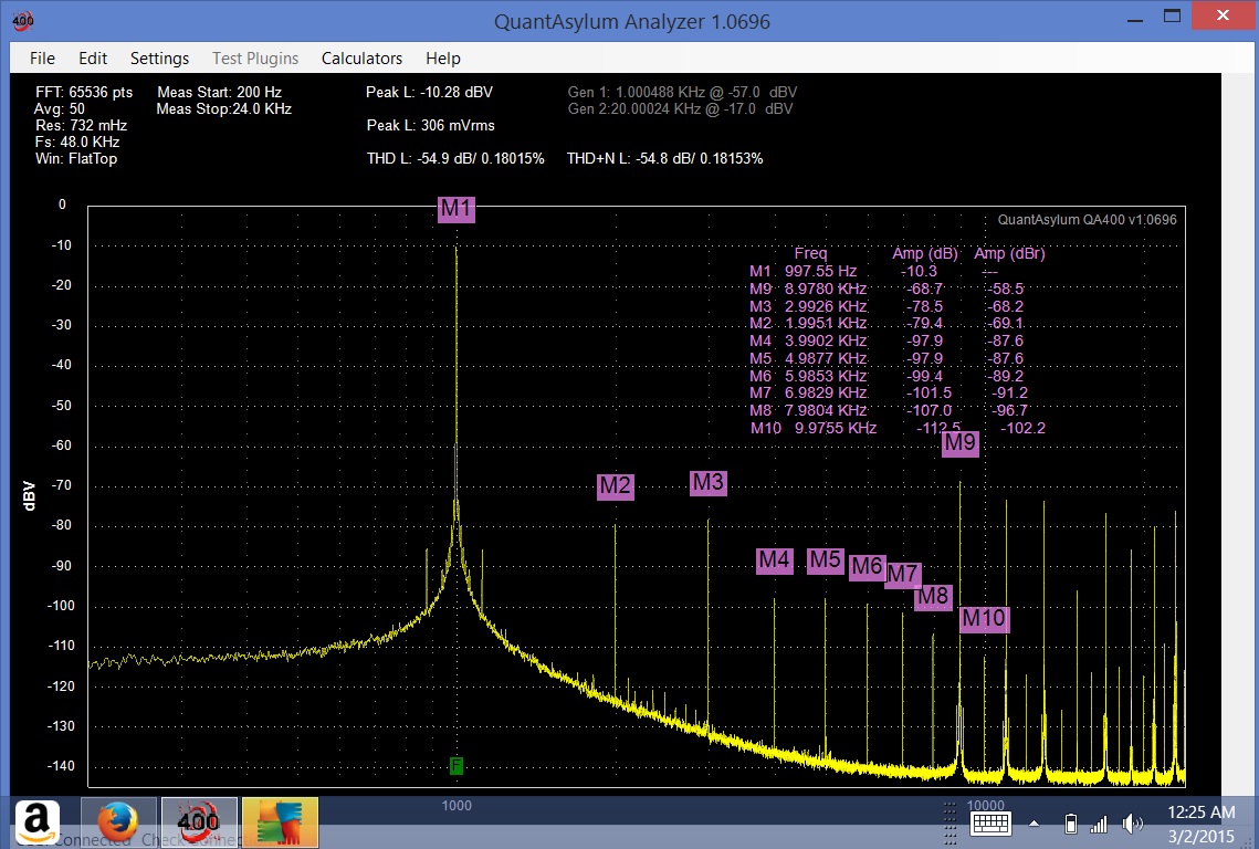
Hi Sync,
This is my LFG1300 spectrum (-10dBV).
0.1% THD is mediocre (and spectral components above 8th are awful), but -as skidave wrote- this is function generator.
My ugly -unmodified- Heathkit IG-18 has lower distortion, but -after setting- practically immovable due to the lamp stabilizer.
This is my LFG1300 spectrum (-10dBV).
0.1% THD is mediocre (and spectral components above 8th are awful), but -as skidave wrote- this is function generator.
My ugly -unmodified- Heathkit IG-18 has lower distortion, but -after setting- practically immovable due to the lamp stabilizer.
Attachments


Euro,
Oh wow, I didn't know. Then I guess I did well
fixing the thing. Mine is right around 0.5 percent distortion.
I was hoping to get that a magnitude lower. Maybe it's not
worth the effort. But how do we know unless we try?
Ok, ski I feel redeemed, just like a coupon, going home.
Oh wow, I didn't know. Then I guess I did well
fixing the thing. Mine is right around 0.5 percent distortion.
I was hoping to get that a magnitude lower. Maybe it's not
worth the effort. But how do we know unless we try?
Ok, ski I feel redeemed, just like a coupon, going home.

Here it is with the components removed:

Then I clipped out the burned out part of the board.
Not pretty but it works, I kept clipping it out until
I got no more carbon going through the board
There is still a bit of heat damage remaining, but
it is just on the surface. Here it is:

Here are the fitted components on the top of the board.

Here is the pic of the bottom of the board:
After carefully chipping away at everything I fitted a new proto board into it.
The first board I tried to fit disintegrated as I was trimming it with
wire clippers.
Then went with a plain G7 type board, which worked as I trimmed it,
then when I started putting the components into it I realized that I need
a board with the back with the solder pads on it. There was no way
that the parts would stay in place without the pads.
On the third board was the charmer, it worked. Careful layout and soldering.
You can see on the right side is an enlarged copy of the layout diagram which
I scanned and then reversed so that I could put everything together properly.
It was tricky, first I highlighted in orange what I needed to do. The I started
with the resistors in the center and moved outwards. Just worked slowly
and carefully adding parts trying to keep it stable as I went along.
I checked and double checked as I went along...trying to make each
bend and not creating a short or open along the way. For some reason
the first two days of putting it together, none of my solder joints looked
good. I can only think because it was sub freezing that everyone must
of been sucking power out of it.
The third day I removed and resoldered all the joints and it worked fine.
I also scraped off between the solder pads to ensure there weren't any
shorts as some of it was pretty tight fit all in all.
It works better than when I received it which is a big plus.
Then I clipped out the burned out part of the board.
Not pretty but it works, I kept clipping it out until
I got no more carbon going through the board
There is still a bit of heat damage remaining, but
it is just on the surface. Here it is:
Here are the fitted components on the top of the board.
Here is the pic of the bottom of the board:
After carefully chipping away at everything I fitted a new proto board into it.
The first board I tried to fit disintegrated as I was trimming it with
wire clippers.
Then went with a plain G7 type board, which worked as I trimmed it,
then when I started putting the components into it I realized that I need
a board with the back with the solder pads on it. There was no way
that the parts would stay in place without the pads.
On the third board was the charmer, it worked. Careful layout and soldering.
You can see on the right side is an enlarged copy of the layout diagram which
I scanned and then reversed so that I could put everything together properly.
It was tricky, first I highlighted in orange what I needed to do. The I started
with the resistors in the center and moved outwards. Just worked slowly
and carefully adding parts trying to keep it stable as I went along.
I checked and double checked as I went along...trying to make each
bend and not creating a short or open along the way. For some reason
the first two days of putting it together, none of my solder joints looked
good. I can only think because it was sub freezing that everyone must
of been sucking power out of it.
The third day I removed and resoldered all the joints and it worked fine.
I also scraped off between the solder pads to ensure there weren't any
shorts as some of it was pretty tight fit all in all.
It works better than when I received it which is a big plus.
Last edited:
Revised Numbers.
Had I bothered to look at SkiDave's handy dandy chart
I would have seen the following:
-46 dB = 0.501187 %
-54 dB = 0.199526 %
-60 dB = 0.100000 %
Spec from the manual is 0.5% so we are doing better.
Right now I'm just about running -55 dB. I can go through
and recalibrate as best as I can and gain another -1 dB to -2 dB.
My plot is from a still open unit.
NOTE: Thought about the low level oscillation that I posted above,
It may be such that I cannot resolve or view the wave on my scope
because it is so long it looks flat and just slowly rises and falls on the
display.
Last edited:
- Status
- Not open for further replies.
- Home
- Design & Build
- Equipment & Tools
- Leader LFG-1300s DOA Fix Then Upgrade