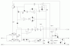
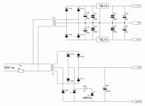
Hi i am thinking of building this power supply i found.
Is there someone who can look at it please as i cant make sense of the 47 ohm pot giving 3 amps. I would very much appreciate it as im not knowledgable enough yet to figure the circuit myself.
0-28V 6-8A Power Supply (LM317, 2N3055)
Is there someone who can look at it please as i cant make sense of the 47 ohm pot giving 3 amps. I would very much appreciate it as im not knowledgable enough yet to figure the circuit myself.
0-28V 6-8A Power Supply (LM317, 2N3055)
The 47 ohm (or 220 ohm) pot limits the base current to the output transistors, not the actual output current. This is not a very good way to do it IMO as it depends critically on device parameters - in this case the beta (current gain) being close to the original devices used during design.
This in general is not a very good design..
This in general is not a very good design..
Thanks guys, im looking at the redcircuits variable dc supply in the hobbys and models section. looks like a good option for one side of my power supply unit. my questions are can i use a 54v center taped trafo with this circuit and if so, should i use higher rated transistors and maybe up the current a bit too?. my power supply when finished will have three sepeate supplys in one box, one 0 to 350v dc and two 0 to 30 ish with variable current limiting. This is so i can use it to power valve and solid state and valve/solidstate amplifiers from one box. also i picked up some nice little lcd panel meters too. i started another thread on on the 350 volt side of things already and had a couple of good ideas posted.... I think : ) Thanks again
...
This in general is not a very good design..
You are being generous. It is a very poor design.
The Redcircuits diagram would want a complete redesign to comfortably output 3A . The conundrum of being able to have a high output voltage with a high current on a variable output voltage circuit such as the "Red" is the power the regulating transistor has to handle when supplying the lower voltages , eg....(redcircuits design) with your transformer would have a max rail volts of 38V dc , say it could maintain 35V on load , when outputing 6V the regulating transistor would be handling 58W at 2A ....up this to 3A and the power is 87W . Bridge rectify the full 54Vac of your transformer and the rail volts becomes 76V ( say it could maintain 70V ) , then outputing 6V the power at 2A becomes 128W .
edit ....i have made no mention of keeping the regulating transistor within its Safe Operating Area or the large amounts of heatsinking required .
edit ....i have made no mention of keeping the regulating transistor within its Safe Operating Area or the large amounts of heatsinking required .
Last edited:
ok so i will just have to go with the red circuits for one output and chuck in a old pc supply for the other 6 and 12 volt fixed voltage output and do a back to back with two big transformers for the 300 volt rail on the fourth output. i will go with the redcircuits for now till i know how to design my own, and buying one would just be far too easy! from my expirience, those who learn the hard way learn the most! : ) thanks for your help epicyclic, and all.
Read up on the LM723 to see how you can make any conceivable supply option. They have been used by the millions in Lambda and other linear supplies: Linear Regulator (LDO) - Single Channel LDO - LM723 - TI.com You can even add foldback current limiting to protect the supply and the load. They have been in use for 40+ years i think.
ok one last question on the red circuits dc supply. I see they are half wave rectifying from 36v center tapped and they say its possible to use up to 48v with the half wave, so i guess that means i could use a 25v non center tap and a full wave bridge? if a transformer at 48 volts is used with half wave rect its 48v*0.707 =34v? then can i use a 25v with bridge recto = 25*1.414 =35v? is that right or have i made a mistake
That is not half wave, that is full wave. half wave would be a single diode with the other half of the transformer winding unused. The two diodes serve the two opposing phases of the AC, thus full wave.
They have a 36vAC center tapped, which means 18-0-18. 18vAC from center tap to either end. You can use a different transformer voltage and a bridge, but this is just as much a full wave.
Your 18v windings will rectify and filter to 25vDC.
If you stuck a 48vAC CT transformer in this, that would be 24-0-24, which would rectify and filter to about 33vDC.
A 25vAC winding with a bridge is the same as a 50v CT winding and the two diodes like this circuit. That would make 35v.
Clearly we are talking estimates, the transformer voltage will vary over loading, and we are ignoring the voltages dropped across semiconductor junctions.
This circuit is rather poor: it has no reference to speak of, and it will drift heavily with temperature.ok so i will just have to go with the red circuits for one output
723 circuits are better in this respect, but they don't let you go to zero for current and voltage without complications and loss of performance
One rarely needs high voltage and high current at the same time from a regulated bench supply.
I find that a lowish current from a regulated dual polarity supply does for most experiments.
On the rare occasions that high current is required then a Low voltage supply is usually good enough. If it needs regulation then I use a current regulator. An adjustable high current CCS is very useful.
I find that a lowish current from a regulated dual polarity supply does for most experiments.
On the rare occasions that high current is required then a Low voltage supply is usually good enough. If it needs regulation then I use a current regulator. An adjustable high current CCS is very useful.
Thanks guys. I have now got 12 volt 2 amp, a 6.3 volt 2 amp and 0-30 volt 2 amp volt/amp variable, actually i built a few different variable supplys from the sugestions made here at diy audio, its all good fun : ) So i have also a 350vdc that i have been using with a breadboard stuck to the top for the voltage devide as needed but i would like to regulate and vary the voltage if poss at that kind of voltage down to about 150, it will be powering a couple 6n2p and two el84 or an ecl86 as a standard. Am i wanting too much?
- Status
- This old topic is closed. If you want to reopen this topic, contact a moderator using the "Report Post" button.
- Home
- Design & Build
- Equipment & Tools
- bench supply

