It does beg a key question; what is the benefit of the designs posted here over the traditional 3 opamp differential amp (like Vogel's)? Saving one opamp is not really an issue in this context. Using a FET input opamp to rais the input impedance is not a problem. Noise may be with two follower opamps at the input. However adding gain could overcome that limitation.
Yes--I have two or three 7A22s and surely a printed manual. This plugin alone makes the hunt for a 7000 mainframe (just got another 7904A in excellent condition) worth it!
Samuel
I got another 7904A, also.... for spare parts and replaced a bad pcb for the digital display readout circuitry. I have included a 7A22 and 7A13 in my stock inventory. The scope plug-in idea was and still is a great concept.
THx-Richard
Last edited:
It does beg a key question; what is the benefit of the designs posted here over the traditional 3 opamp differential amp (like Vogel's)? Saving one opamp is not really an issue in this context. Using a FET input opamp to rais the input impedance is not a problem. Noise may be with two follower opamps at the input. However adding gain could overcome that limitation.
BW - You lose the CF BW enhancement 100kHz is easy even at G >1000
Noise - with FET op-amps 1.0nV would be difficult.
Otherwise it is sort of a wash.
If you can find old EDN design ideas you might get a laugh out of "Stacked In-amps Lower Noise".
Last edited:
BW - You lose the CF BW enhancement 100kHz is easy even at G >1000
Noise - with FET op-amps 1.0nV would be difficult.
Otherwise it is sort of a wash.
If you can find old EDN design ideas you might get a laugh out of "Stacked In-amps Lower Noise".
Scott what is the CF in CF BW?
It does beg a key question; what is the benefit of the designs posted here over the traditional 3 opamp differential amp (like Vogel's)? Saving one opamp is not really an issue in this context. Using a FET input opamp to rais the input impedance is not a problem. Noise may be with two follower opamps at the input. However adding gain could overcome that limitation.
For me, it's cheaper to replace a blown JFET pair than it is to replace a blown OPA827!
I was very interested in Mr. Groner's approach, although I don't need quite so many BF862's in parallel. I appreciate that he drew the servo and inverted servo!
The so called current feedback.
So a wider BW is achieved by feeding back to the source, or emitter if bipolar, than through the gate or base? Is this because the FB current is higher?
I think he's referring to the (first-order) gain independence of current feedback topologies WRT bandwidth. With voltage feedback (and conventional dominant-pole compensation), the bandwidth is inversely proportional to closed loop gain. With current feedback, it is independent from closed loop gain because the transconductance of the input stage scales with it.
Samuel
Samuel
I think he's referring to the (first-order) gain independence of current feedback topologies WRT bandwidth. With voltage feedback (and conventional dominant-pole compensation), the bandwidth is inversely proportional to closed loop gain. With current feedback, it is independent from closed loop gain because the transconductance of the input stage scales with it.
Samuel
Thanks. I'll dig up some math on it. CF is less familiar to me.
Now that this relatively old thread has been brought up, I simulated a bit on Scotts circuit from post #16.
Does anyone have a good idea on how to eliminate the offset from the LSK389?
Ideally a kind of servo, adjusting the offset to a few uV on the input, or whatever the servo op-amp allows in terms of accuracy.
Or would a manual adjustment have that kind of accuracy over a (limited) temperature range?
A calibration cycle, e.g. at power-up, could also be an option. Provided the circuit will be reasonably stable after that.
I have looked at some ideas, but they do have some potential issues.
I would like to have a gain of e.g. 100.
I have not really thought about your problem, but I remember an application note (AN 124) from Jim Williams 775 Nanovolt Noise Measurement for A Low Noise Voltage Reference | Analog Devices
Yes, I have seen application note 124.
The "problem" with the principle in AN 124 is that it will adjust the circuit parameters until the gates of the two FET's are at the same voltage. But this won't work with a current feedback amplifier because the gates will have different voltages ( = input voltage), even with (theoretical) perfectly matched FET's.
I have designed a couple of different circuits, which I expect to test in the near future. One design is for a DC coupled application. The other one will mostly be for AC signals. But these are based on voltage feedback.
Jens- I meant to post this a while ago.
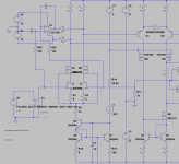
This uses a chopper stabilized opamp to correct for input offset at the output of the input pair. it works pretty well. I was using this a a DC coupled phono preamp with 80 dB of gain. In practice well under 1 mV of offset at the output. There are newer better chopper opamps with much higher frequency chopping making it easier to keep that noise out.
The simulation may need some models not in the LTC database.
Attachments
Demian,
Thanks for your input. The servo part looks similar to what I had in mind. I plan to use the OPA191, which is not a chopper op-amp, but it has a very low offset and a much lower noise than the LTC1150. I have also used longer time constants. In my simulation, I get only an insignificant increase in noise level compared to using no servo. Time will tell if that will also be the case in real life!
Thanks for your input. The servo part looks similar to what I had in mind. I plan to use the OPA191, which is not a chopper op-amp, but it has a very low offset and a much lower noise than the LTC1150. I have also used longer time constants. In my simulation, I get only an insignificant increase in noise level compared to using no servo. Time will tell if that will also be the case in real life!
The OPA191 should be fine. I was trying for less than 1 uV offset input referenced which was an artificial goal and not really obtainable with audio cables. Steering current at that inner differential works quite well. You need to know the sensitivity etc. to get it right and keep the opamp's output centered in normal operation. I tried to scale the gain so the noise contribution of the opamp is minimized.
First, many thanks to Scott for sharing his differential preamp (post #16). I have built a couple and they work nicely.
However, is there a clever way of AC coupling this preamp?
My current application is for piezoresistive pressure sensors. These sensors are Wheatstone bridge type devices with 1000-1500 Ohm source impedance, which makes RC filters on the preamp inputs problematic. The AC coupling corner frequency does not need to be particularly low. 50-100 Hz is low enough for this application.
Any suggestions are very welcome,
Jonas
Why?1000-1500 Ohm source impedance, which makes RC filters on the preamp inputs problematic.
Scott has disabled his account. He's badly missed.Any comments, Scott ?
- Home
- Design & Build
- Equipment & Tools
- Differential take on Groner's LN Measurement Amp