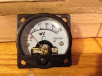
This is really back to basics. I have used nothing but digital multimeters and panel meters in the past, but decided to buy 2 analog panel millivoltmeters to display anode currents in a tube amp, because they look cooler; hopefully one of them is shown below. I measure the input impedance at 13 ohms in both of them.
Am I missing something? Should there be some kind of circuitry in front of this thing to increase the input impedance to maybe the megaohm range, where it would be useful. Could they both be defective?
I tried writing the manufacturer, but of course got no response.
Thanks in advance for your help. This is embarassing.
Mike
Attachments
Perhaps they are actually ammeters, which would explain the low input impedance.
Perhaps fullscale, 100% needle deflection represents 100 microamperes rather than 100 millivolts.
You could rig up a variable power supply, a 100K series resistor, and a couple of DVMs, to tickle the meter and find out. If I were you, I'd make a 3 column table: V_across_meter, I_thru_meter, Front_panel_indication. Then I'd plot the data in Excel and see whether one of the curves is a straight line that passes through the origin.
Hi,
Fundamentally all meters are ammeters, deflection is related to passed current.
Fundamentally the lower the current required for full scale, the better the meter.
Your missing some fundamental simple electronics. Series high value resistor
to turn it into a voltmeter. Parallel low value resistor to turn it into a ammeter,
and some very tricky details if you want to measure any sort of high currents.
rgds, sreten.
Thanks for your help. I've never used anything with needle-deflection, except for a VTVM decades ago in college. I can't imagine this is a good meter, but I'll put a large resistor in series and calibrate it, I guess.
The meter is being used to measure voltage across a 1 ohm resistor.
The meter is being used to measure voltage across a 1 ohm resistor.
On safety grounds I would use them to measure the currant at the cathode as the zero adjuster screw may end up live or may not be insulated to withstand the HT voltage.
All the safety warnings that come with mains powered bench volt meters both digital and analogue apply to the meter itself.
If you are measuring currant you just allow for the resistance of the coil in the meter and use ohms law to work out the shunt resistor value. Also you could just calibrate it with a preset pot.
Hi,
The meter insulation in good for (floating) 1000V.
Yes you just slap a big resistor in series with it and calibrate.
It may have its current rating printed on the back.
FWIW predigital the specification that mattered for your
meter was Kohm/V. 3K was basic, 10K decent and 20K,
a 50uA full scale meter movement, the quality standard.
Not that it matters much measuring the voltage across
a 1R resistor, but it matters a lot across a 1M resistor.
This was the business when I was young :
http://www.shinjo.info/frank/instruments/AVO/Instruments/Avometers8/MkI&IIuser.pdf
rgds, sreten.
The meter insulation in good for (floating) 1000V.
Yes you just slap a big resistor in series with it and calibrate.
It may have its current rating printed on the back.
FWIW predigital the specification that mattered for your
meter was Kohm/V. 3K was basic, 10K decent and 20K,
a 50uA full scale meter movement, the quality standard.
Not that it matters much measuring the voltage across
a 1R resistor, but it matters a lot across a 1M resistor.
This was the business when I was young :
An externally hosted image should be here but it was not working when we last tested it.
http://www.shinjo.info/frank/instruments/AVO/Instruments/Avometers8/MkI&IIuser.pdf
rgds, sreten.
Last edited:
The ARRL "Radio Amateur's Handbook" (revised and published every year) used to have a pretty good section about the classic D'Arsonval meter movement, how to determine the sensitivity (true range) of an unknown meter movement, calculate series/shunt resistors for use as voltmeters or ammeters, etc. To be honest, I haven't looked at one since the turn of the millenium but they are fairly common in public libraries as well as college and university libraries, and used book stores. I suspect any of the annual volumes from about 1940 up to 2000 or so would have the information you need.
Dale
Dale
What needs to be done is to determine the sensitivity of the meter (ie, x amps = full scale), then determine the shunt resistance required to create the new scale.
I don't remember off the top of my head the test procedure for determining the sensitivity, but it isn't difficult. Most meters seem to use a standard, eg. 50μA or 100μA. I'll see if I can post a good test procedure.
I doubt you'll need a series resistance. The meter operates via current through its coil; it is only the scale that is calibrated and marked for voltage.
What range of current are you looking to display?
Thanks. At 7.8ma, the needle deflects fully to 100mV, and I measure 100mv across the unit with an accurate digital voltmeter. So that makes the input resistance about 12.8 ohms (100/7.8), I think.
I want to measure (milli)voltage across a 1 ohm resistor (at the cathode). I don't want to put this unit in series and measure current directly.
But I still haven't figured out how to do it with this beauty. Putting a large series resistor in there seems like it would reduce the current so much that there would be no needle deflection at all.
I'll look at allaboutcircuits.com or something similar to see how to get the input impedance up, although I guess putting 12.8 ohms in parallel with 1 ohm is not the worst thing in the world.
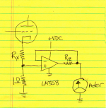
You could install a gain-of-1 buffer amplifier between the current sensing resistor, and the meter. Here's one way to do it, using a "single supply opamp" (which continues to function properly when inputs and output are all the way down at its bottom supply rail).
The voltage across the 1 ohm sense resistor, is copied to the opamp output at gain = +1.000, and applied across your meter. Resistor Rz is optional, you can replace it with a short circuit (Rz = 0) if you wish. It limits the current through the meter if things go haywire. Opamp input impedance is > 100K ohms, output impedance before current limiting is extremely low, thanks to NFB.
The voltage across the 1 ohm sense resistor, is copied to the opamp output at gain = +1.000, and applied across your meter. Resistor Rz is optional, you can replace it with a short circuit (Rz = 0) if you wish. It limits the current through the meter if things go haywire. Opamp input impedance is > 100K ohms, output impedance before current limiting is extremely low, thanks to NFB.
Attachments
Hi,
Presumably there is some internal stuff in the meter if it literally
indicates 100mV with 100mV applied. However near 10mA
is nothing like the sort of current a meter usually needs.
That implies around 100R/V which is simply godawful.
A very cheap movement will do > 1K/V, < 1mA fullscale.
rgds, sreten.
Last edited:
Hi Mike, yup, I expect there is a shunt resistor fitted internally....I have never seen a moving coil meter measuring such low internal resistance natively.......I measure the input impedance at 13 ohms in both of them.
Am I missing something?
Mike
If you open the meter, you should be able to remove this internal shunt, and wire the movement directly to the terminals.
Then you can use external series resistors (trim pots) to set the sensitivity that you require....ie no need for external amplifier circuitry complexity.
Regards, Dan.
That does not quite make sense ?......8.3ma to full deflection, 98ma across the terminals at full deflection.
Mike
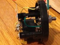
Are their many turns on the moving coil, can you post a close-up pic of the coil please.
Dan.
Dan,
I took it apart and there is no shunt resistor. There is just a 4 ohm resistor in series between the input and the movement.
Rechecked everything. 8.3ma to full deflection, 98ma across the terminals at full deflection.
Mike
Hi,
Fair enough, it is what it is, designed to indicate 100mV
across some point that has a low source impedance.
You still haven't said what voltage (hence current) range
you want the meter to indicate, across 1R it will indicate
~ 0 to 100mA .
rgds, sreten.
It is always A GOOD THING to use some kind of amplifier to feed a moving coil meter, which is what you have.
The reason is that they are not very forgiving of overload and/or reverse connections.
Many years before the flood, I worked as a tech in a production test lab straightening pointers (gulp!), replacing meters (expensive even then) and finally adding a protection op-amp so that;
1) forward current could not exceed 120% of FSD
2) reverse current could not exceed -10% of FSD (ish)
Easy to do with diodes and a DC coupled amp.
Edit: so have a look at your circuit and see what is the worst case fault mode for the meter.
BTW I still use an AVO model 8 wherever possible. Much easier to believe it rather that jumping digits when fault finding.
Cliff
Last edited:
- Status
- This old topic is closed. If you want to reopen this topic, contact a moderator using the "Report Post" button.
- Home
- Design & Build
- Equipment & Tools
- How to use a millivoltmeter :(