That is not a reliable method at all: it will give many false answers.Assuming therer is no datasheet, is there a better way of determing the EBC Pin layout of a transistor other than getting the base and measuring the highest reading to get the emitter ?
You have either to test the forward and reverse beta (with a multimeter for example), or the B-E reverse breakdown voltage (at low currents, obviously, and not for low noise transistors).
Using only a multimeter in diode mode, once you have identified the base, you measure with the supposed collector shorted to the base, it should be reliably lower than if it is the emitter that is shorted.
Another possibility is to compare the reverse capacitances: Cbe>Cbc
AVO 8 + slightly moist finger determines whether an unknown device is npn or pnp in seconds and identifies both this and pin-outs with uncanny ease in two or three (and sometimes one if you get lucky) measurement. That one measurement even "indicates goodness" by demonstrably showing gain and any leakage, something that eludes the common multimeter.
Such is progress though (bring back the swinging brick)
Such is progress though
(bring back the swinging brick)Finding a base is easy, but to find the emitter, you need an analog meter with 9volts battery for the high resistance scale. When reverse biased with this meter set to high Res scale, the EB junction will show low resistance as the breakdown voltage is 5.X volts. No way you can find it reliably with a DMM.
Gajanan Phadte
Gajanan Phadte
what about this
what about this...Peak Electronic Design Limited - Atlas DCA - Semiconductor Analyser - Model DCA55 I dont own one but would like too...
what about this...Peak Electronic Design Limited - Atlas DCA - Semiconductor Analyser - Model DCA55 I dont own one but would like too...
#2 sounds most like what I'd do. My cheapo multimeter has a diode tester and an hFE tester. With the diode tester, you can find out whether it's NPN or PNP, and which lead is the base. Then with the hFE tester, you can figure out which is which between the emitter and collector.could posters 2, 3 & 4 expand on their test method?
For example, I just tried it with a 2N3053 from the junkbox. Connected one way, I got a reading of hFE = 85. After switching the collector and emitter connections I got hFE = 4. So the first guess was obviously correct.
could posters 2, 3 & 4 expand on their test method?
You take one AVO 8 and set it to "ohms X 10K" which is the high ohms range utilising the 15 volt battery.
You connect the two leads to the unknown device and interpret the result. That one action is "step one"
1) You get no reading at all. This is when you have got lucky
With the leads still on the transistor you firmly press a finger onto either lead and touch another finger of the other hand onto the unconnected lead (or use the finger of the same hand if the method and transistor package allow). The meter will either swing over toward full scale perhaps reaching 20 to 100K) or remain displaying an open circuit. That's all the info you need...If the black lead was the lead needed to be touched to provide a small base current via the fingers, then the device is NPN. The meter swinging hard over (remember 100K on an AVO on this range is quite near FSD) shows the device has at least reasonable gain.
If the meter didn't swing over in that test then the finger is on the "wrong" lead but the device is now identified as PNP. Using the "finger test" on the other lead (red one) will again show gain with the meter swinging over.
2) You get a reading of around 400K in the first step. That indicates you have correctly identified C and E but the polarity is wrong. You can still determine NPN or PNP though from that one reading. If its NPN the red lead will be on the collector. Vise versa for PNP.
3) You get a "low" reading of around 30 to 50K in step one. That indicates you have correctly identified the base. Confirmation is provided by moving one lead over to the other transistor lead. If that to reads the same (low) then the lead that was stationery is the base. Black lead on the transistor pin indicates NPN. Vise versa for PNP.
4) You get a "medium" reading of say 300K in step one. That indicates you are across B and E with reverse bias.
5) You get a "high" reading of say 2Meg ohm. That indicates you are across B and C with the junction reverse biased.
I did not read it (since I don't have access to an AVO 8).
The expanded versions were intended for those Members who with less experience would not be able to follow the short versions in posts 2, 3 & 4.
I have a different method that seems to work and seems not to damage devices.
Turn on the hFE test on a DMM.
Insert the device in the ebc or bce holes. Does it read?
Turn it around 180degrees and test the two locations ebc & bce again, does it read?
Now change from NPN to PNP and repeat the 4 options.
Only 1 of the 8 possible orientations will give a sensible hFE reading. That solves it for me.
BTW,
I bought a new fairly cheap handheld last week.
It has a "new" way that I have not seen before to measure hFE.
A 2pin adaptor is inserted into the DMM. It has only three holes for the transistor legs.
First problem, it is not universal as a the 4hole ebce is.
Second problem. It reads wrong, very high hFE are predicted.
It must have some electronics inside the adaptor that converts the 2pin connection into a 3pin test.
One nice thing, the spec sheet gives the Ib and Vce for the hFE test. This is the first time I have seen this stated.
Last edited:
I have an (ancient as in early 1980's) SOAR LED DVM with an hfe facility. Using a method like yours, only one way will give a sensible reading.
Elvee made the excellent and not widely appreciated point that its easy to permanently degrade the noise figure and forward beta of certain devices when applying "random" forward and reverse bias conditions to the junctions.
Elvee made the excellent and not widely appreciated point that its easy to permanently degrade the noise figure and forward beta of certain devices when applying "random" forward and reverse bias conditions to the junctions.
I basically use godfrey's method: first pick the base, which also tells polarity, and then the Hfe meter gives *wildly* different readings, so no confusion possible.
By the way, I have to use it often because I get 2N5401 , which I use as the differential input pair in my power amps, in 2 different pinouts, and often mixed in the same order.
For some weird reason, they and their brother 2N5551 are the only ones where I have that potential problem.
None other (BC546/556/etc.) .
In an analog meter the red lead gives negative voltage and the black lead gives out positive voltage.
Connect the base of an NPN transistor to red and connect the black lead to emitter with the meter in high ohms range. Keeping the base connection, connect the black to collector. You will find that the BE connection shows much lesser ohms than the later.
This happens because the reverse breakdown voltage of the BE junction is around 5.X volts and the BC junction has more than 30 Volts for the same.
Remember, whatever be the Vcbo, all the transistors' BE reverse breakdown voltage is always 5.X volts.
If you do the above procedure in a low ohms range where a 1.5V battery is used in the ohms range, u will find both the readings are nearly same.
Gajanan Phadte
I use methods in posts #4 and #8...same end result.
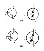
See jpg...transistors measure like diodes with dmm (or vom) set to diode scale.
I have found that the red lead provides positive output but check your dmm or vom before using.
I use a 9V battery and a 1K resistor to find the emitter.
See jpg...transistors measure like diodes with dmm (or vom) set to diode scale.
I have found that the red lead provides positive output but check your dmm or vom before using.
I use a 9V battery and a 1K resistor to find the emitter.
Attachments
Last edited:
- Status
- This old topic is closed. If you want to reopen this topic, contact a moderator using the "Report Post" button.
- Home
- Design & Build
- Equipment & Tools
- Determing EBC of transistors