The grass comes from the shared USB ground. What works for me is to run the PC from a battery (laptop) and then run a separate ground to the chassis or the USB ground from the DUT so power ground and signal ground are separated. Inside the power ground and the signal return get mixed at some stage when there is current passing through the signal return line.
This is why the differential I/O is really essential. Its a problem with every other non-isolated high gain device I have as well.
Bear-
When the distortion is that low talking in dB makes the numbers easier to grasp. Is there a dB option for the display? I think you are showing around -120 dB for the second harmonic.
Yes I can just push a button and show dBx where x=dBv or dBu iirc...
...I am unsure about the calibration of the VP-7725 as well as some of the subtleties of operation. The buttons seem to do some unexpected things in terms of results and also there are a range of options that are intuitively unclear to me. Never could find even a users manual, even in Japanese!
Here there was no DUT. Also I saw no diff in running from batt or power... not sure there is a shared ground path between the two instruments and the USB ground or not. Regardless the grass dropped 10dB with nothing connected to the QA.
The 7725 has differential inputs. Push a button, two BNCs come alive.
So, what is the opinion on the source of the extra spurs, the input opamp??
_-_-bear
I have had the grass growing on the bottom of the FFT display and I have been able to be rid of it.... as Demian said, it all needs isolation and care with ground paths... and shielding. Doing that is not a P-n-Play operation for most people. But if Demian or another can find the time to complete and get something useful as an add-on product or a DIY project installed inside a QA400 -- what ever -- then it will be more P-n-Play and useful for a test instrument capable of utilizing a greater amount of the potential of it's 24 bit system.
Fortunately, the alternative of professional instruments have already taken all this into consideration and such type of unwanted noise/spurious signal pickup is not an issue when using their test equipment. Even with single-ended DUT.
[BTW -- I use an ac line Isolation transformer (Topaz) and a 3-2pin adapter on the power plug output for USA to keep ac grounds isolated. PC is plugged into it. And it is plugged into a very good ac power line filter for extreme noise isolation]
Thx-RNMarsh
Last edited:
Yes I can just push a button and show dBx where x=dBv or dBu iirc...
...I am unsure about the calibration of the VP-7725 as well as some of the subtleties of operation. The buttons seem to do some unexpected things in terms of results and also there are a range of options that are intuitively unclear to me. Never could find even a users manual, even in Japanese!
Here there was no DUT. Also I saw no diff in running from batt or power... not sure there is a shared ground path between the two instruments and the USB ground or not. Regardless the grass dropped 10dB with nothing connected to the QA.
The 7725 has differential inputs. Push a button, two BNCs come alive.
So, what is the opinion on the source of the extra spurs, the input opamp??
_-_-bear
You would need an exceptional differential input to see the junk your trying to remove. Usually you just get mode noise.
Run a separate wire from the VP to a ground on the QA400. It takes some experimentation to find where to connect. Also experiment with the grounded/isolated options for the VP chassis.
You will still have some effects from the measurement process. The signal is a differential at around 2V P-P. I don't think the opamp is limiting the performance.
You may be able to get a manual for the VP7725 here: KAI-Products information: Test & Measurement Instruments and Power Supplies since they are now the distributors in the US. I found this really detailed datasheet: http://www.kikusui.co.jp/common/product/pdf/levear/levear_aa_vp77xxx.pdf You may be able to figure out most of what you want from it.
We should see if the powers that be at DIYaudio are up for making a "repo" for service manuals.
What of looking at the analog input section (between it and the A/D) of the QA for the harmonic spurs?
That's "louder" than the grass ever is...
If the spurs can be eliminated via changing the opamp(s), then that's a pretty big deal.
_-_-
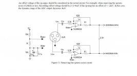
Bear the op amps are OPA1641. Two for each channel making up a balanced drive for the ADC. The op amps have to be a rail to rail to have enough swing to meet the Vpp conditions. The op amps are supplied by a 10Vdc single ended supply and biased from the VCOM buffer through a 100k ohm resistor. The VCOM is buffered with another OPA1641.
What's in front of that is a 1K resistor, IIRC a 10uF ele and an ESD chip.
That's the front end of the QA400.
Mmmm... well those spurs are raising up from somewhere.
Looks like the OPA1641 *ought* not be able to produce these spurs. Wondering if it is something amiss in the power supply doing that?
I am with you up to "VCOM", wazzat?
Demian, thanks for that link! I have sent an email to the rep, he's probably frothing at the mouth with the prospect of a sale, so more likely to cooperate I expect.
_-_-bear
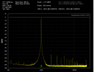
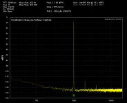
Below are three quick tests I just made with the QA400. It was my laptop on battery to QA400 to generator. I tried a separate ground from the generator to to the QA400 but saw no difference.
First is left, second is right and third is loopback on left. All I see is harmonics with some really low level noise. What I don't understand is why the distortion numbers are different when the plots are pretty much the same. That's to be checked and pursued with Matt when I have time.
First is left, second is right and third is loopback on left. All I see is harmonics with some really low level noise. What I don't understand is why the distortion numbers are different when the plots are pretty much the same. That's to be checked and pursued with Matt when I have time.
Attachments
Mmmm... well those spurs are raising up from somewhere.
Looks like the OPA1641 *ought* not be able to produce these spurs. Wondering if it is something amiss in the power supply doing that?
I am with you up to "VCOM", wazzat?
Demian, thanks for that link! I have sent an email to the rep, he's probably frothing at the mouth with the prospect of a sale, so more likely to cooperate I expect.
_-_-bear
Bear one thing you can try, which if IIRC did have an effect on the spurs, is to lower the VCOM coupling resistance from 100K to 10K. Crystal recommends this value in the app section of the data sheet. The value was increased in the QA400 because it is this resistor that sets the nominal input impedance.
It's easy to just solder a leaded resistor across the SMT part.
There is an offset circuit described in the AKM application section which addresses spurs.
I haven't seen this technique in Crystal's literature but it might work with the Crystal ADC's. The input circuitry for Crystal and AKM is almost identical.
Hi Demian,
I have actually saved a screen plot of the QA400 in loopback. From time to time I have noticed that I seem to get a very clean spectrum of only 2nd and 3rd, but for most times I get a spectrum similar to yours. Have you seen anything similar?
I have the plot on my laptop. Let me see if I can figure out how to upload a picture.
Mogens
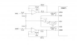
This is the exact input circuit used in the QA400. The codec used is a CS4272.
A 1K series resistor was added between the input cap and VCOM resistor and an ESD chip after the 1k resistor. The 10k resistors were replace with 100k. Otherwise the circuit is identical to what's in the QA400. The VCOM of the CS4272 is called VQ1 on the CS4271.
A 1K series resistor was added between the input cap and VCOM resistor and an ESD chip after the 1k resistor. The 10k resistors were replace with 100k. Otherwise the circuit is identical to what's in the QA400. The VCOM of the CS4272 is called VQ1 on the CS4271.
Attachments
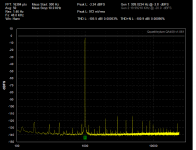
Attempt to upload Picture. Please notice that I captured this while my QA400 was un-caibrated on the laptop and I can't remember if I ran on batteries or with the charger plugged in. In any case, I have seen this also when connected to my stationary.
Am I beeing fooled here?
Mogens
Am I beeing fooled here?
Mogens
Attachments
Attempt to upload Picture. Please notice that I captured this while my QA400 was un-caibrated on the laptop and I can't remember if I ran on batteries or with the charger plugged in. In any case, I have seen this also when connected to my stationary.
Am I beeing fooled here?
Mogens
Nope that's what it should look like.
This is the exact input circuit used in the QA400. The codec used is a CS4272.
A 1K series resistor was added between the input cap and VCOM resistor and an ESD chip after the 1k resistor. The 10k resistors were replace with 100k. Otherwise the circuit is identical to what's in the QA400. The VCOM of the CS4272 is called VQ1 on the CS4271.
Ok, a few datasheets later...
AK5394a. The exact nature of "VCOM" or "VQ1" is a bit unclear. AK calls it out as a reference voltage but that no current can be drawn. "VCOM is a common voltage of the analog signal". Eh? What does that mean?
AK5394AVS.pdf
Then they show the bias voltages being derived from the power supply rail and ground via a divider, not from VQ1/VCOM.
But here:
AK4620BVF.pdf
We see in figure 19 for example, the same harmonic spurs emerging with a signal at or near 0dbfs. This chip has similar performance.
I did not run across the app note that speaks of the spurs, got a link or an idea where to look?
The CS part: CS4272_F1.pdf seems to have similar performance. Both parts appear to have about 110dB max usable range. This conforms to what the QA is doing rather closely.
Interestingly AK is showing a 32bit (!!) part, I didn't look at the sheet yet.
So, I'm thinking that these spurs are an artifact of the A/D itself and not anything in the analog pre section.
The only thing that I could come up with is that crosstalk might be reduced by the use of two opamps, one per channel, to buffer the VCOM voltage.
Also, if dropping the value of the 100k bias resistors to 10k actually helps the spur issue, perhaps the way to go is to drop it lower and put a low distortion outboard buffer to drive the input??
No app note I know of. I meant app section of the data sheet.
Yes I think the spurs are a product of the ADC but also noise at the inputs. Digital noise will do this. Lowering the impedance at the input attenuates noise pickup. A field across a smaller resistance means less V across the resistance. The noise can't generate enough current in a low ohm resistor to amount to much. It's all proportional.
Yes I think the spurs are a product of the ADC but also noise at the inputs. Digital noise will do this. Lowering the impedance at the input attenuates noise pickup. A field across a smaller resistance means less V across the resistance. The noise can't generate enough current in a low ohm resistor to amount to much. It's all proportional.
I didn't see any reference to the relationship between the resistor value and the spurs. I can understand resistor noise, but it's unclear to me how added noise (1/f?) at the input of the A/D causes harmonically related spurs to occur. An explanation or perhaps a reference/link/citation might be good to read.
So the next question is what is the relationship between the resistor value and the spurs? If we go down to say 1k, 100 ohms or 25ohms what is gained? It ought to be possible to build up a buffer that can drive 25 ohms and still maintain sufficiently low distortion...
Perhaps applying the bias at the output might be advantageous? Like the old class A opamp pull up?
_-_-
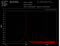
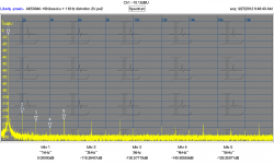
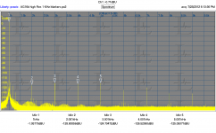
The offset in the AK5394A datasheet moves the zero away from digital zero, which moves away from a difficult area for all audio ADC's. Below are 2 measurements of an ultra low distortion oscillator by a tweaked AK5394A. There are still harmonics. All the harmonics are below -118 dB and you can also see some 60 Hz stuff near the fundamental. The first was measured at 2V in with 4 V representing full scale. The second at 4V with much higher resolution. I'm not sure I trust the harmonics, since the oscillator drift could reduce them. The bins are approx .05Hz wide in this measurement and it takes more than 5 minutes to make. I believe this is the current state of the art performance possible with an ADC. It also shows that a bigger microscope will always show more problems.
The Vref is a critical point in the ADC and lower impedance + lower noise reduces harmonics and residuals in the output. Getting that right is difficult since its ground reference needs to match the input perfectly but not cause other noise issues in the chip. Single ended power makes this even more difficult because the chip ground also needs to deal with all the digital switching currents.
The Vref is a critical point in the ADC and lower impedance + lower noise reduces harmonics and residuals in the output. Getting that right is difficult since its ground reference needs to match the input perfectly but not cause other noise issues in the chip. Single ended power makes this even more difficult because the chip ground also needs to deal with all the digital switching currents.
Attachments
- Home
- Design & Build
- Equipment & Tools
- QuantAsylum QA400 and QA401