I have a power supply with an AC output (0-22V, 4A). I want to use this output to simulate the secondary of a power transformer, not having to worry about circuit protection for now.
I wanted to use my oscilloscope (a Tektronix analog scope) to look at the effect of load variation from my regulation circuit.
I have the following problem: when I connect the tip of the oscillloscope probe, then the common, the voltage of the power supply drops significantly (as can be seen on the power supply display) and after 5 seconds the circuit breaker of the unit goes off. I made several test, I even succeeded at blowing the 2 amp fuse of the unit.
After some tests, I also noticed that using the DC output has the same effect. I switched probes, same results. I also verified with a multimeter (battery powered) there is no voltage drop between the oscilloscope and the unit grounds.
When I use my PC oscilloscope, this does not happen.
Does anybody have an idea of what could be wrong here? I never had any problem with the scope before.
Here is my guess:
The analog scope ground is connected to the AC safety ground and your power supply is the equivalent of a btl output. You are actually shorting one of the outputs to ground.
Solution(s):
If your scope has two inputs then connect the two probes to the two AC feeds and use the A-B function to view the difference.
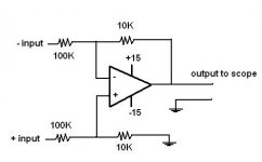
OR build a differential to SE opamp cct that divides by 10
Always watch out for smoke.")
The analog scope ground is connected to the AC safety ground and your power supply is the equivalent of a btl output. You are actually shorting one of the outputs to ground.
Solution(s):
If your scope has two inputs then connect the two probes to the two AC feeds and use the A-B function to view the difference.
OR build a differential to SE opamp cct that divides by 10
Always watch out for smoke.
Attachments

- Status
- This old topic is closed. If you want to reopen this topic, contact a moderator using the "Report Post" button.
- Home
- Design & Build
- Equipment & Tools
- Power supply and oscilloscope problem