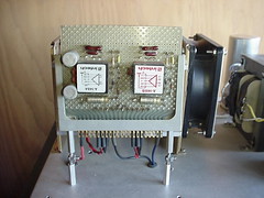
The power amp test fixture can be used to test power amplifier, voltage regulator and preamp boards. It has a chimney heat sink to accommodate up to 8 power transistors and two 44-pin edge card connectors. The test boards are mounted on a standard Vector board with the 44-pin edge card configuration. I have designed several regulators, RIAA equalizer amps and power amps using the 44-pin edge card configuration.
The power supply is designed to provide +/- 22V and +/- 44V. The next upgrade will include voltage regulators with adjustable voltage, adjustable current limit and current monitor. Speaker and RCA connectors will also be added.
FIXTURE SIDE

VOLTAGE REGULATOR 1

VOLTAGE REGULATOR 2

MX 50 COM

RIAA
RCA 70

The power supply is designed to provide +/- 22V and +/- 44V. The next upgrade will include voltage regulators with adjustable voltage, adjustable current limit and current monitor. Speaker and RCA connectors will also be added.
FIXTURE SIDE
VOLTAGE REGULATOR 1
VOLTAGE REGULATOR 2
MX 50 COM
RIAA
RCA 70
Last edited:

The test fixture regulators are designed to allow adjustable voltage and current limit to protect the amp during initial testing. Once the amp is working, it can be connected to the power supply caps.
The power supply regulators are designed to allow the current limit to be adjusted form a few milliamps to several amps. The voltage range is 7 to 40 V with an input voltage of 45 V. The same circuit will be used for both +V and –V regulators with different components. The wire wrap plug board was built with DIP sockets to allow the parts to be replaced with different values and testing of both +V and –V regulators.
The scope pic shows the load transient recovery time and level, the current was switched form 150 mA to 1.15 A. C1 was removed for the test.
Attachments


An autotransformer allows the power supply voltages to be adjusted from 0 to 44 V. To bring up an amp safely, a current limit circuit with adjustable current is used with both power supplies. Once the amp is fictional and the bias is adjusted to the desired level the current limit circuit is bypassed for full power testing.
Attachments

Power amp test fixture schematic with the +/- current limit circuit.
Attachments

Last edited:

What do you think is a fast, easy and flexible way to slap a heat-sink on and off a prototype power amp's OPS mounted on an L-bracket??
I want to temporarily use the heat sink for other projects so it cant be bolted on.
THx-RNMarsh
I want to temporarily use the heat sink for other projects so it cant be bolted on.
THx-RNMarsh
What do you think is a fast, easy and flexible way to slap a heat-sink on and off a prototype power amp's OPS mounted on an L-bracket??
I want to temporarily use the heat sink for other projects so it cant be bolted on.
THx-RNMarsh
That's a good idea. Small wood working "C" clamps are available in several verities. A strip of wood could be used protect heat sink fins.
- Status
- Not open for further replies.
- Home
- Design & Build
- Equipment & Tools
- Power Amp Test Fixture