I am busy collecting parts to build Mr Millett's regulated tube high voltage Bench Power Supply. Link - High-voltage bench supply
Has anyone done a successful build. Any tips and tricks?
Has anyone done a successful build. Any tips and tricks?
Millett + Millett Power Supply w/ Revised Schematic
I discovered the Pete Millett HV Power Supply many years ago, in a search for what to do with a TEK 120-120 PST I found on FleaBay. Since then I've collected 3 Heathkit regulated power supplies (PS3, PS4, IP32) which work great, but lack UMPH.
Well, I "got retired" last year (shades of TubeLab George) and so now it's SOLDER TIME, boys & girls.
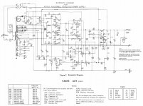
First, I redrew Pete's schematic in a more traditional regulated PS ("stacked") format (top to bottom: pass, error amp & regulator tubes). I posted a PDF below.
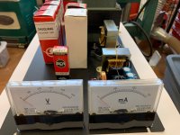
Please notice the Millet Regulated DC Filament Supply board on schematic & in photos. This has worked great (with remote Bourns 10T pot) with my Flexi-Amp for my mono system, which takes most DHTs and even 46 tetrodes with a 417a driver with CCS on top. The TEK PST is an unwieldly monster, but it DOES have lots of nom 6.3V taps available...might as well make some old tubes feel happy.
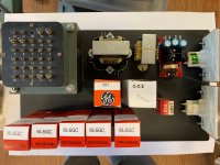
Second, arrange parts on a 17x10 inch Hammond cover (the steel chassis is in the mail). See photos below.
Third, Comments & Questions:
(1) NB on original schematic there are TWO C9s: first bias supply cap, and 630V 0.1uF ceramic to the B+ Adjust pot wiper.
I made the ceramic cap C13.
Please double check this schematic against the original before you use it (!)
If anyone wants the *.dwg file, to tinker with, pls PM me.
(2) the schematic shows actual voltage on the TEK 120-120 HV taps at 118 VAC primary off a variac. The nominal 6.3V taps were all about 6.86V.
I'm not worried about the HV taps being a little over spec, but I would like to get the filaments down by 10-15%. What's the best method? Brute force series resistor? Voltage divider resistors? Buy a couple more Millett Filament boards?
(3) I vaguely understand the PMillett current limit concept, but can't work-out what current corresponds to each Zener diode voltage. Can anybody help with that?
(4) I have lots, I mean LOTS of Sylvania 6AV5GA sweep tubes (the "good" ones) which I could use as Pass tubes; this would presumably allow a higher output voltage than the 6L6GCs. There's plenty of filament amps available to run the 6AV5 sweep tube (1.2A each versus 0.9 for 6L6 family); the extra draw might even pull the voltage down closer to 6.3V.
However, 6AV5 plate dissipation is officially only 11 watts (although I am running them ultra-linear at 340-350Vp and nearly 23 watts dissipation DAILY with no troubles, knock wood).
I can't figure out what would limit the 6AV5GAs in this application; voltage, current or both (ie power). It obviously doesn't help that I don't have a real world (i.e. ~23 W) VA curve. Can anybody help wrap my head around this?
Can I just offset the "official" curve and draw a box under that?
I'm pretty sure TubeLab George would say to wire-up one socket for a 6AV5, stand back, and crank the voltage pot with a fiberglass broom handle.
Fully instrumented, of course. With a GoPro focused on the plates. Multiply results X5.
Given the lack of data, that may actually be the best idea.
Comments gratefully accepted.
I discovered the Pete Millett HV Power Supply many years ago, in a search for what to do with a TEK 120-120 PST I found on FleaBay. Since then I've collected 3 Heathkit regulated power supplies (PS3, PS4, IP32) which work great, but lack UMPH.
Well, I "got retired" last year (shades of TubeLab George) and so now it's SOLDER TIME, boys & girls.
First, I redrew Pete's schematic in a more traditional regulated PS ("stacked") format (top to bottom: pass, error amp & regulator tubes). I posted a PDF below.
Please notice the Millet Regulated DC Filament Supply board on schematic & in photos. This has worked great (with remote Bourns 10T pot) with my Flexi-Amp for my mono system, which takes most DHTs and even 46 tetrodes with a 417a driver with CCS on top. The TEK PST is an unwieldly monster, but it DOES have lots of nom 6.3V taps available...might as well make some old tubes feel happy.
Second, arrange parts on a 17x10 inch Hammond cover (the steel chassis is in the mail). See photos below.
Third, Comments & Questions:
(1) NB on original schematic there are TWO C9s: first bias supply cap, and 630V 0.1uF ceramic to the B+ Adjust pot wiper.
I made the ceramic cap C13.
Please double check this schematic against the original before you use it (!)
If anyone wants the *.dwg file, to tinker with, pls PM me.
(2) the schematic shows actual voltage on the TEK 120-120 HV taps at 118 VAC primary off a variac. The nominal 6.3V taps were all about 6.86V.
I'm not worried about the HV taps being a little over spec, but I would like to get the filaments down by 10-15%. What's the best method? Brute force series resistor? Voltage divider resistors? Buy a couple more Millett Filament boards?
(3) I vaguely understand the PMillett current limit concept, but can't work-out what current corresponds to each Zener diode voltage. Can anybody help with that?
(4) I have lots, I mean LOTS of Sylvania 6AV5GA sweep tubes (the "good" ones) which I could use as Pass tubes; this would presumably allow a higher output voltage than the 6L6GCs. There's plenty of filament amps available to run the 6AV5 sweep tube (1.2A each versus 0.9 for 6L6 family); the extra draw might even pull the voltage down closer to 6.3V.
However, 6AV5 plate dissipation is officially only 11 watts (although I am running them ultra-linear at 340-350Vp and nearly 23 watts dissipation DAILY with no troubles, knock wood).
I can't figure out what would limit the 6AV5GAs in this application; voltage, current or both (ie power). It obviously doesn't help that I don't have a real world (i.e. ~23 W) VA curve. Can anybody help wrap my head around this?
Can I just offset the "official" curve and draw a box under that?
I'm pretty sure TubeLab George would say to wire-up one socket for a 6AV5, stand back, and crank the voltage pot with a fiberglass broom handle.
Fully instrumented, of course. With a GoPro focused on the plates. Multiply results X5.
Given the lack of data, that may actually be the best idea.
Comments gratefully accepted.
Attachments
Comparing the General Radio 1205-B Power Supply
Stumbled onto the manual for the General Radio 1205-B regulated power supply. See attached.
Also: https://aafradio.org/docs/GR_1205-B_Rev_C_manual_1965.pdf
Several surprises here.
(a) puts 200 mA through a pair of 6AV5GA pass tubes
(b) HOWEVER, the 6AV5GA pass tubes are down-stream of a pair of 5727 "thyratrons control rectifiers" (a MIL version of a 2D21, I guess) which may be taking the brunt of the "switching" load (if that's the right terminology).
The dot on the tube schematic indicates a gas-filled tube.
Apparently, thyratrons were used in high-voltage switching applications (e.g. radars).
Seems like an unnatural cross-breeding between a triode and a gas-filled VR tube, but functions pretty much like a thyristor of an SCR (silicon controlled rectifier) which I understand.
As a bonus, thyratrons apparently EMIT X-RAYS (!) which apparently reeked havoc with early radar technicians...
Attachments
- Status
- This old topic is closed. If you want to reopen this topic, contact a moderator using the "Report Post" button.