A couple of issues, if you average the FFT analysis of an oscillators output you might miss amplitude modulation of the harmonics that would indicate gain hunting. A cepstrum would be better for that.
The wider the sweep range the more the gain shifts and the more range the gain control element requires. The more range of the gain control element the more its distortion contributes.
All of the component parts have improved over the years. It was very interesting to see in Jim Williams last design the use of "tweak" parts from Oscon capacitors to really low distortion resistors in locations he thought were critical.
I currently use a transversal filter for my basic oscillator design. The longer it is the lower the distortion to the component and switch accuracy. In the basic form it is nowhere near any of the units considered here. It's strength is accuracy of frequency control and consistent output level. Issues that don't seem as big here, but are critical for some of my tests.
It isnt that it is of no interest. rather the amplitude regulation has been so good as not to worry. But, what do you use for a Cepstrum?
I have replaced quit a few passive parts to lower distortion. Resistors, capacitors and trim pots/controls... switch contacts, etc.
What do you test that needs a super accurate freq control and output level?
Thx-RNMarsh
I have replaced quit a few passive parts to lower distortion. Resistors, capacitors and trim pots/controls... switch contacts, etc.
What do you test that needs a super accurate freq control and output level?
Thx-RNMarsh
Hmmmm. The AD633 has a unused and grounded summing input to the buffered/multiplier output.Hmmmmm.
Thx-RNMarsh
And, another AD633 can be made as a freq doubler off the osc output...... and a sample of it put into the first 633's summing input. Got some AD633 on order. But will try to do a test of concept first.
-RNM
I just wonder exactly how important the rectification is given some adequate method of filtering ripple -- and when in the Cordell SVO the ripple frequency was cut in half and the ripple level increased by 6dB without any consequent penalty, well, I wonder.
Very much a function of how much the multiplier is decoupled. In the design I'm working on the multiplier is decoupled about 4x more than it is in the AP System One. That's about the limit I've found to still get a dependable 10 s settling time to 0.1% for a 100 Hz to 10 Hz range change. With such a configuration, the level detector ripple at the lower harmonics (fundamental to 3rd or 4th) needs to be in the "few dozen uVrms" range to keep its distortion contribution below the -150 dB level. This is feasible with a very good dual sample-and-hold level detector, without additional low-pass filtering. With less multiplier decoupling, the requirements for level detector ripple quickly become hopeless.
So, where do You think the weak link is in these existing products/designs?
No idea, I haven't analyzed them in such detail. In a well-designed product such as the System One the various distortion sources are likely kept at similar level, such that there is an overall well-balanced cost-performance ratio.
My goal has been for multiple freqs output at below -140 THD+N or better.
As all I'm writing is old news for you I'm confident you've already measured the noise floor of a typical oscillator topology--just for the others which may have not: this can be done by snipping the multiplier control voltage port off and feeding it with an external low-noise DC voltage which is just a weeny bit lower as the one which makes the oscillator oscillate. Then feed the oscillator output, which is now a funny narrow-band noise signal, to a THD+N analyzer manually set to the same frequency as the oscillator (the notch is required as near the oscillation frequency the voltage noise density becomes very large, and this frequency band is removed in a THD+N measurement too). This measurement procedure ignores amplitude modulation noise from the leveling loop, but is still a pretty good way for a first estimate.
With reasonable impedance levels and available IC opamps, it's difficult to push the noise floor much below -110 dBu (22 kHz BW) up to 20 kHz. So for your -140 dB THD+N the oscillator operating level would need to be in the order of +30 dBu!
At -140 dB and below passives may become a roadblock.
Definitely, particularly as the operating level of the oscillator needs to be relatively high for good THD+N, as the above discussion showed. I'm currently working out the details of the output attenuator, and it looks like I'll need several dozen resistors as series/parallel configuration!
Samuel
Well,
You are already there! You are already playing in a high league.
-140dB is a 100.0E-9 ratio and for a 5V RMS it's 0.50 uV = 500nV
Cheers
Hp
We are already at the -140dB/ <.00005% THD+N level using this fast-track approach. Can we go lower - into the noise?
Thx-RNMarsh
You are already there! You are already playing in a high league.
-140dB is a 100.0E-9 ratio and for a 5V RMS it's 0.50 uV = 500nV
Cheers
Hp
It isnt that it is of no interest. rather the amplitude regulation has been so good as not to worry. But, what do you use for a Cepstrum?
I have replaced quit a few passive parts to lower distortion. Resistors, capacitors and trim pots/controls... switch contacts, etc.
What do you test that needs a super accurate freq control and output level?
Thx-RNMarsh
For the cepstrum I am still using a DOS program as it seems I am one of the very few who look at it.
I am only 1/3 way through reading this thread so I apologize for repeat some of the earlier issues.
There are two reasons for looking at amplitude variations. The dynamic changes really are amplitude modulation. A .1 db variation is about 1% modulation which then raises the issues of at what frequency is that dynamic variance. Of course these appear as sidebands. Such sidebands can mask "base spreading" which is an indicator of voltage coefficient noise.
Now overall level change with frequency is a sign that the gain control element has to have greater range and thus more contribution to distortion.
Most of the tests that I am getting to require the oscillator is locked to the analyzer. Then you can use a very fine time delay to look at the phase artifacts.
Although doing fine and finer THD and noise is quite challenging, looking else where seems to be more productive for measuring artifacts that affect perceived quality.
ES
I see. Well, I'm pretty confident that it is possible to design oscillators with better distortion performance than presented in this thread, without resorting to fundamentally new approaches. The first step to improve a given design is to understand the dominant distortion mechanism. We have four known fundamental distortion sources--passives, opamps, multiplier and level detector ripple. To find out which one's the culprit, it is best to measure each one in isolation. Just looking at the oscillator output (as you've done it so far) is not very helpful. This applies particularly because various distortion sources may cancel. If you swap in another opamp type and observe that the oscillator output has lower distortion, this may have two reasons. First, it could be that indeed the old opamp was the dominant distortion mechanism, and the new one is better. Or it could be that the new one actually has higher distortion, and that happend to cancel better with another distortion source. There's no way to decide which one's the case if you just look at the oscillator output. But if you hit the second one and believe it's the first, you'll get tremendously fooled and run in circles forever. So looking at each of the four known fundamental distortion sources in isolation is absolutely inevitable.
So we need to know how this can be done. The passives may be checked on a suitable bridge setup, or you can replace them with series-parallel combination which lowers their distortion contribution. The opamps can be measured at high noise gain (luckily a Swiss chap has already done much of this hard work for you). The multiplier can be isolated in the oscillator and tested by feeding it with a suitable sine input and DC control voltage. Level detector ripple distortion contribution can be estimated by operating the oscillator and taking an FFT of the voltage at the multiplier control voltage port. The various frequencies can be translated into resulting harmonic distortion levels by the simple amplitude modulation equation.
That's a lot of work, but before thinking how to make it better we need to know what's the issue...
Samuel
Samuel, this is a great observation. I've tried to do a bit of this when I was upgrading the oscillator in my THD analyzer, and it is indeed a lot of work. I had focused on the agc detector and the JFET control element, but not in as rigorous a way as you suggest. I piddled around with changes in each of those circuits that should have made a difference, and was able to infer what was dominating. For example, I might double the filtering on the agc control signal, temporarily sacrificing settling time, to see if the oscillator distortion would go down. For the JFET, I altered the relationship between JFET operating signal level and the injection factor of its correction signal into the oscillator loop.
But I like your more thorough approach more.
Cheers,
Bob
yes. I include noise and distortion reduction in the process. I believe progress is made by getting away from the jFET to reg level. It improved THD byat least 6db across the board with same oscillator IC.
Thx-RNMarsh
Hi Richard,
Sorry if the answer came up before. This thread is great, but fast-moving and I sometimes can't keep up.
Can you describe specifically how you measure the oscillator noise, and what numbers you got for one of the better oscillators you measured?
I'd like to measure my oscillator for noise in the same way to see how it compares.
Cheers,
Bob
Hi Richard,
Can you describe specifically how you measure the oscillator noise, and what numbers you got for one of the better oscillators you measured?
I'd like to measure my oscillator for noise in the same way to see how it compares.
Cheers,
Bob
I am looking at the notched output of residual harmonics from the analyzer monitor output. I am using an analog swept wave filter type analyzer - HP-3580A.
The monitor output is scaled to the analyzer range selected with a normalized output level of 1v rms = full scale (fs) of the range selected. The range is on its lowest from a ShibaSoku AD725D analyzer which is -110dB (.0003% fs). The noise floor from this monitor port is about -160dB re fs.
The dynamic range of the HP is >85dB on its 0db/1v range.
The signal level from the generator being measured is 7v rms.
Thx-RNMarsh
Last edited:
For the cepstrum I am still using a DOS program as it seems I am one of the very few who look at it.
Although doing fine and finer THD and noise is quite challenging, looking else where seems to be more productive for measuring artifacts that affect perceived quality.
ES
Which software program... I have DADisP.
I have no idea what I would need such thd levels for other than what it might tell us about subtle things and how/why undestandings... R&D. Also makes for a lazy/easier test without subtracting out the system artifacts afterwards in post processing. I dont want the test equipment intruding in my DUT testing results. And, finally, it is a challenge to improve upon the work of others who have already spent a great deal of their life understanding ultra-low distortion and oscillators. I am standing on the shoulders of thier great study and learning from their example and taking it from the point where they left off.... around the edges in most cases.
Many of the commercial hardware audio THD analyzers have not been updated and some dropped from some catalogs... leaving a good deal of surplus, relatively low cost equipment to upgrade. The topologies are often very good... just need updated parts for 20dB improvement. Standing on their work and shoulders is a very good place to start.
Recently, I have begun to think of distortion cancellation techniques rather than lowering the distortion... I think this can produce fruitful results and understandings as an alternative to parts of the oscillator design.
Thx-RNMarsh
Last edited:
OK, you have everything. I give up!
Yes I do.... because I have my good health and a great buddy, Lisa.
btw - DADisP is in DOS under the screen.
Boy, you gave up too easily. I dont accept.... No Tap-Out. Keep spending on test equipment and learning... the U.S. economy needs you to spend our way back to good economic health!
-Richard
Last edited:
OK you convinced me I'll splurge on the SRS 1. Now you have to match. Next I'll mention to Sam that my arithmetic says his noise floor of 2.45 uV or 16.5 nV/Hz is way too high. Just to get everyone grouchy! (I think I did the arithmetic correctly otherwise I'll get grouchy...spent the day fixing a current probe.)
Samuel, this is a great observation. I've tried to do a bit of this when I was upgrading the oscillator in my THD analyzer, and it is indeed a lot of work. I had focused on the agc detector and the JFET control element, but not in as rigorous a way as you suggest. I piddled around with changes in each of those circuits that should have made a difference, and was able to infer what was dominating. For example, I might double the filtering on the agc control signal, temporarily sacrificing settling time, to see if the oscillator distortion would go down. For the JFET, I altered the relationship between JFET operating signal level and the injection factor of its correction signal into the oscillator loop.
These are surely valid approaches. Another interesting experiment is observation of the distortion at the three outputs of a SV oscillator. If the distortion drops when going from highpass to bandpass to lowpass it is likely either from the multiplier or level detector ripple. If it stays ~constant, opamps/passives are more likely.
One important advantage of the isolating approach I suggested is that the resolution requirements for the distortion analyzer is much relaxed. Most of these measurements can be done with a decent soundcard-based setup, even for an oscillator aiming at the magic -140 dB. When looking at the oscillator output directly the (usually not well known) distortion contribution of the analyzer quickly rises eyebrows (not everybodys, but at least mine).
Next I'll mention to Sam that my arithmetic says his noise floor of 2.45 uV or 16.5 nV/Hz is way too high.
The noise floor of an oscillator is not white, as near the oscillation frequency the noise gain of the opamps, and the amplification of thermal noise from the resistors and the multiplier output, becomes very high. Most of the noise energy is concentrated in this frequency band. Deriving an analytical expression for the output voltage noise density of a SV oscillator ought to be major fun!
The -110 dBu I mentioned are for the upper end of the audio frequency range. At lower frequencies noise drops considerably (within a constant 22 kHz measurement BW), because of the lower cutoff-frequency of the lowpass filter formed by the integrators and the, relative to the measurement bandwidth, narrower range around the oscillation frequency with very high noise gain.
Samuel
I am looking at the notched output of residual harmonics from the analyzer monitor output. I am using an analog swept wave filter type analyzer - HP-3580A.
The monitor output is scaled to the analyzer range selected with a normalized output level of 1v rms = full scale (fs) of the range selected. The range is on its lowest from a ShibaSoku AD725D analyzer which is -110dB (.0003% fs). The noise floor from this monitor port is about -160dB re fs.
The dynamic range of the HP is >85dB on its 0db/1v range.
The signal level from the generator being measured is 7v rms.
Thx-RNMarsh
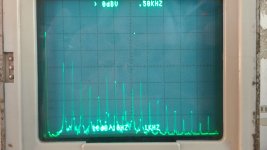
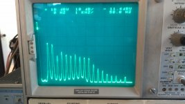
I not getting the same spectra as you are. Attached is the same distortion analyzer output on both a swept analyzer (7L5) and an FFT (Wavetek Plugin for 7K). The only difference is 10 seconds versus 100 seconds for the swept output. In both cases the top line is -100 dB from the fundamental. They do not look like what you are getting.
The distortion analysis output does not show noise between the harmonics. Looking at that noise is not an indication of the noise from the source. You need the monitor output to look at that.
Attachments
The noise floor of an oscillator is not white, as near the oscillation frequency the noise gain of the opamps, and the amplification of thermal noise from the resistors and the multiplier output, becomes very high. Most of the noise energy is concentrated in this frequency band. Deriving an analytical expression for the output voltage noise density of a SV oscillator ought to be major fun!
The -110 dBu I mentioned are for the upper end of the audio frequency range. At lower frequencies noise drops considerably (within a constant 22 kHz measurement BW), because of the lower cutoff-frequency of the lowpass filter formed by the integrators and the, relative to the measurement bandwidth, narrower range around the oscillation frequency with very high noise gain.
Samuel
Samuel,
You seem to have all the details well thought out. I'll wait to see your finished result before running an analysis. To me the major improvement you have mentioned is the dual sample and hold.
You also seem to have used your analyzer to look at the control signals. I assume you've also done that at very low frequencies.
SV filters have a number of interesting quirks. There are ways to reduce some of their noise, but I am pretty sure you've at least played with them.
Do let me know if you settle on carbon composition resistors for the output divider!
(Or at least RC compensation.)I look forward to building one.
But for now I will stick with my master oscillator injected eight oscillator bank (If I can find it) for now.
ES
I not getting the same spectra as you are. Attached is the same distortion analyzer output on both a swept analyzer (7L5) and an FFT (Wavetek Plugin for 7K). The only difference is 10 seconds versus 100 seconds for the swept output. In both cases the top line is -100 dB from the fundamental. They do not look like what you are getting.
The distortion analysis output does not show noise between the harmonics. Looking at that noise is not an indication of the noise from the source. You need the monitor output to look at that.
Hi Demian,
I'm having a little trouble seeing the top line. Can you put some numbers to this.
What is the noise floor you are measuring compared to what Rick has reported?
The noise floor of an oscillator is not white, as near the oscillation frequency the noise gain of the opamps, and the amplification of thermal noise from the resistors and the multiplier output, becomes very high. Most of the noise energy is concentrated in this frequency band. Deriving an analytical expression for the output voltage noise density of a SV oscillator ought to be major fun!
Agree, an interesting observation that when I was experimenting with the precision TC resistors as gain control, at the moments of quasi-static stability the noise sidebands dropped suddenly to ridiculusly low values.
Both plots are identical. 8 10 dB divisions with the top at 1V which translates to -100 dB. The first two harmonics at at around -138 dB. The rest closer to -150 dB. The space between the harmonics is not representative of the noise of the oscillator.
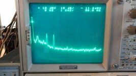
Attached is a measurement from the distortion monitor output of the 725 of the same source. The top line is -90dB on this output. Both the second and the third harmonics are at -130 dB and the rest below the noise except for a little of the 5th poking up above the noise.
The spread near the fundamental is several things. First, its representative of the filter/windowing you are using. Second it can be both amplitude and frequency noise (Phase noise). RC 0scillators don't have the high Q of a crystal and will have more close in noise. They are not really stable enough to even do an ADEV measurement which is another way of looking at that noise.
Attachments
- Home
- Design & Build
- Equipment & Tools
- Low-distortion Audio-range Oscillator