I just got one of the prototypes today. Its definitely promising but not quite ready for prime time. I will probably buy several. I'm sure we will hear more soon on it. When I have been able to do a proper shakedown I'll report back to them. Still much nicer than the big FFT. I use a Wavetek FFT plugin for a Tek 7000 scope which works well but still has the size issue. However adding even a laptop to the bench is still a lot of real estate.
I think the QA400 needs an analog input conditioner. making an autoranging one would be nice but overkill probably. It should have differential inputs, switchable to 100V RMS, 10V RMS and 1V RMS input and protected to not fry with 300V. It should also have active differential outputs that will maintain the differential voltage even if one side is shorted, possibly with a calibrated attenuator. I think this can be done with a handful of parts today, far less than was required 20 years ago. It would be useful for other interfaces as well as the QA400.
I think the QA400 needs an analog input conditioner. making an autoranging one would be nice but overkill probably. It should have differential inputs, switchable to 100V RMS, 10V RMS and 1V RMS input and protected to not fry with 300V. It should also have active differential outputs that will maintain the differential voltage even if one side is shorted, possibly with a calibrated attenuator. I think this can be done with a handful of parts today, far less than was required 20 years ago. It would be useful for other interfaces as well as the QA400.
Okay so where are you all getting your pots from? I'm kind of stuck with Digikey and Newark as second. Everything is mail order where I am.
Cheers,
David.
For the two null adjust trimmers, the center wiper goes directly to 15vdc; I used Spectrol cermet multi-turn trimmers (500 Ohm); 3/8th inch square. Now sold thru NTE Electronics Inc. Avail at Mouser. USD 1.50. They have multi-finger precious metal wiper for long term set point reliability and excellent wiper contact. -RNM
Last edited:
I just got one of the prototypes today. Its definitely promising but not quite ready for prime time. I will probably buy several. I'm sure we will hear more soon on it. When I have been able to do a proper shakedown I'll report back to them. Still much nicer than the big FFT. I use a Wavetek FFT plugin for a Tek 7000 scope which works well but still has the size issue. However adding even a laptop to the bench is still a lot of real estate.
I think the QA400 needs an analog input conditioner. making an autoranging one would be nice but overkill probably. It should have differential inputs, switchable to 100V RMS, 10V RMS and 1V RMS input and protected to not fry with 300V. It should also have active differential outputs that will maintain the differential voltage even if one side is shorted, possibly with a calibrated attenuator. I think this can be done with a handful of parts today, far less than was required 20 years ago. It would be useful for other interfaces as well as the QA400.
Hi Demian,
QuantAsylum is shooting for a price target of US 200.00 on this. There is talk of an external
unit that adds balance. I've mentioned the front end to them. This is why I suggested using the 339a as a front end for this and sound cards. We get all this short of the balance. Some form of ground isolation would be nice as well.
Yes it is very much still beta but I think it has great potential.
Cheers,
Last edited:
 I'll settle for the Spectrol.
HP339A results -
I am pretty happy with the results so far. With promise of even better results to come --- I started in this direction after my FFT in an Audio-Precision went south... its oscillator still met specs but the FFT was giving bogus numbers which didnt match what the self-cal said.... so, the A-P is in Thailand now being repaired by ex-AP distributor/repair people... if they can. So, in the mean time, I was trying other FFT stuff and other sources etc etc. With the changes/mods, and especially with davada's great work/help on it the 339A is again a nice bench, stand alone, instrument now for GP work. Next up, a better FFT system to use with it or other sources. -Thx RNMarsh
I am looking for a nice clean sine wave source of variable freq - that i can then run thru a passive filter notch. I plan to use a high quality ADC/DAC system to measure the thd and FFT it in computer. Before that I had 2 fixed freq oscillators from Victor via eBAY. I bought a couple 339A as junk/parts units to cobble into one working unit... but, we shall see. --- --- Thx-RNMarsh
I am pretty happy with the results so far. With promise of even better results to come --- I started in this direction after my FFT in an Audio-Precision went south... its oscillator still met specs but the FFT was giving bogus numbers which didnt match what the self-cal said.... so, the A-P is in Thailand now being repaired by ex-AP distributor/repair people... if they can. So, in the mean time, I was trying other FFT stuff and other sources etc etc. With the changes/mods, and especially with davada's great work/help on it the 339A is again a nice bench, stand alone, instrument now for GP work. Next up, a better FFT system to use with it or other sources. -Thx RNMarsh
Those numbers are constrained by the bandwidth and input circuit requirements. They don't reflect the residual distortion of the circuits. If you measure the individual distortion components and add them the number can be much lower typically. If you have a bandwidth of 30 KHz or 80 KHz the THD+N will be greatly affected by the noise.
My ShibaSoku 725 (you played with it) has a residual of -115 per spec. in analysis mode, where its actually looking at just harmonics. In normal mode, with the same input etc. the number becomes -102 because of the noise. In practice it seems significantly better than that.
Making a low noise input brings issues of dynamic range and damage from overload.
If we could devise an overload system that is lightning fast but is out of the way in normal operation we could not only have lower noise but distortion as well. Maybe some sort of switched clamp. I suspect the 339a input protection diode string is getting in the way. With levels above 0dB the distortion takes off. One more thing to look at.
Does anyone know what the dual gate FET is for in the input protection circuit? There sure is a lot of 2nd H on the TP of the output of the FET. Does this cancel 2nd H of the diode string???
Does anyone know what the dual gate FET is for in the input protection circuit? There sure is a lot of 2nd H on the TP of the output of the FET. Does this cancel 2nd H of the diode string???
THD vs. THD+N
Here is an example of THD vs. THD+N. This is a measurement of my KH4400A. The THD is -117 dB/ .00013% but THD+N is -97/.0014%, a 20 dB difference and the noise floor is in fact quite low. Its just the effect of the energy inside the frequency band.
I will collect the different protection solutions I have docs for and we can see what there is to learn. There are anumber of different tricks used in different products. To meet the CE spec most measurement instruments need to be able to withstand something like 300V without damage (or becoming a hazard to the user) so there are a lot of good solutions.
Attachments
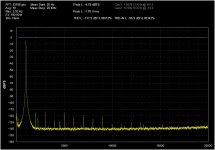
Hi Demian -- something isn't correct here -- I RMSed the first 9 products using my little Excel worksheet and got 0.00035%, -109dB. I assumed that the fundamental was at 0dBFS. If it is lower, and it seems to be lower than -4dBFS, then the THD is even higher than I calculated.
Edit -- with fundamental at approx -5dBFS, the THD is -104, 0.00064%
Edit -- with fundamental at approx -5dBFS, the THD is -104, 0.00064%
Last edited:
Comparing specs from Audio instrument makers ($$) --- SRS model SR1 the residual thd+n is spec'ed at -106 to -112dB. The AP 2700 is spec'ed at -112 to -115dB. I want better, unfortunately. Thx-RNMarsh
Noise floor (22KHz BW) is -118dB spec on the SRS. Now there is some fudging going on with both examples... like using 3-4 volts of output as ref. In any event, it looks like < -120 is pushing things pretty hard in analog domain for wideband sources/testers. -RNM
Comparing specs from Audio instrument makers ($$) --- SRS model SR1 the residual thd+n is spec'ed at -106 to -112dB. The AP 2700 is spec'ed at -112 to -115dB. I want better, unfortunately. Thx-RNMarsh
The Christmas tree bulb was better than that out of the box.
Hi Demian -- something isn't correct here -- I RMSed the first 9 products using my little Excel worksheet and got 0.00035%, -109dB. I assumed that the fundamental was at 0dBFS. If it is lower, and it seems to be lower than -4dBFS, then the THD is even higher than I calculated.
Edit -- with fundamental at approx -5dBFS, the THD is -104, 0.00064%
You are right, the calculation is off somewhere. I got different numbers the second time I tried it. Beta software. . .
Can you post a link to the spreadsheet?
My point was that the broadband noise can make even really low numbers not so low. And the THD+N meters (any of these older units) only measure the combination.
The Christmas tree bulb was better than that out of the box.
Here is an idea, use a DC voltage added to the AC across the bulb to steer the absolute output level.
Here is an example of THD vs. THD+N. This is a measurement of my KH4400A. The THD is -117 dB/ .00013% but THD+N is -97/.0014%, a 20 dB difference and the noise floor is in fact quite low. Its just the effect of the energy inside the frequency band.
I will collect the different protection solutions I have docs for and we can see what there is to learn. There are anumber of different tricks used in different products. To meet the CE spec most measurement instruments need to be able to withstand something like 300V without damage (or becoming a hazard to the user) so there are a lot of good solutions.
Hi Demian,
What OS are you running QA400 on?
Hi Demian -- something isn't correct here -- I RMSed the first 9 products using my little Excel worksheet and got 0.00035%, -109dB. I assumed that the fundamental was at 0dBFS. If it is lower, and it seems to be lower than -4dBFS, then the THD is even higher than I calculated.
Edit -- with fundamental at approx -5dBFS, the THD is -104, 0.00064%
I't works out to .000607% THD.
Hi Demian,
What OS are you running QA400 on?
Win 7 64 on I5 w/ 6 GB of ram.
I'll try it on the other systems in the next few days. It seems to crash a lot on this system.
The Christmas tree bulb was better than that out of the box.
that one and several others as well. Whats up with these companies not being SOTA in lowest harmonic distortion attainable... and at their prices, too?? [no need to answere] -RNM
When I used the thd+noise instrument from Demian, it was reading on my little amp... .0005% . Too close to the test equip residual? The FFT output was uncalibrated so that didnt help. can it be easily/accurately calibrated? Looking for a test system to easily and accurately measure harmonics in the .00001 - .0001% area. Thx-RNMarsh
Last edited:
Win 7 64 on I5 w/ 6 GB of ram.
I'll try it on the other systems in the next few days. It seems to crash a lot on this system.
Smoking.
What version of software do you have?
Last edited:
- Home
- Design & Build
- Equipment & Tools
- Low-distortion Audio-range Oscillator