I was talking about analyzers in general and in particular the inability to actually correlate reading from a traditional analyzer to one using FFT or similar techniques. And in more general terms why the FFT noise measurement in about he same band as an analog instrument in many cases seems higher. This is really only relevant when comparing e.g. an AP 555x or Shibasoku 735 to something like an RTX with any of several software packages. I believe some is due to the need to lower the level for lowest distortion but the noise comes up by the reduced level. Its all a difficult conundrum to resolve. And probably meaningless except for number obsessives (distortion nuts). Something I need to consciously disengage from.
Noise in THD+N in conventional analog THD analyzers can be a a tough nut to crack, as there are numerous sources and many do indeed get worse at smaller signal levels. However, one that is particularly troublesome is phase noise in the fundamental that can result in added noise and also imperfect elimination of the fundamental. This phase noise can come from the oscillator or from the notch filter circuit in the analyzer. For example, if you drop the operating signal level in the oscillator down in order to reduce oscillator THD, for example by reducing the signal level across a control JFET), oscillator noise will be increased. This will result in phase noise about the center frequency in addition to ordinary wideband noise. Phase noise in a fundamental interferes with complete notching out of the fundamental.
This shortcoming in such an analyzer can be mitigated, and distortion measurement floor reduced, by passing the residual output of the analyzer through a spectrum analyzer and measuring the harmonics themselves.
Cheers,
Bob
That's a very good result! I must try to duplicate that.
In the second graph, how many averages are used?
Jan
Not near so many as in the first one, 15 to 20 not sure exactly.
I am also more than satisfied.
It will be interesting to see your measurement too.
And the same 1kHz signal at max. level-almost 3V, measured with notch on most sensitive RTX6001 input (0,1V), exhibits no visible harmonics.
One thought struck me that the graph shown no noise floor 'suck out' near the notch. I think this means that the noise floor displayed has more to do with the input to the analyzer / soundcard noise floor, and does not portray the oscillator noise floor. If you added a preamp post-notch, perhaps 40dB, you could safely increase the residual above the soundcard noise floor and probably get a lower overall system residual.
According to Victor, notch harmonics attenuation is app. 9dB for the second harmonic and app. 5dB for the third harmonic, so in the worst case 2H is at app. -156dB and 3H at app. -159dB down.
Victor max with notch on 0,1V TRX input.png
I think it'd be a good idea to just measure your notch directly. Just measure the gain at 2kHz and 3kHz and you have the conversion factors actually in your notch - no need to quote something else. I guess you need a general purpose oscillator for that, but for measuring gains, it doesn't have to be that clean at all to be useful. A sine wave generated by a computer sound card would be more than acceptable, as long as the frequency was correct. But, you can verify that using the same spectrum analyzer SW.
Fine tuning a twin T notch
When using a deep twin T notch for measurements, very exact fine tuning is necessary to obtain the deepest notch. While it is true that a twin-T requires three sets of matched R & C pairs, and that tuning typically requires all 3 R's to be changed together, for very fine tuning is is quite effective to make small changes in just the shunt R.
Cheers,
Bob
I agree and i am quet happy with analyzer ability. I was concerned before, couldn't get the result as i get now.I think this means that the noise floor displayed has more to do with the input to the analyzer
Yes, i'll try that, thanks.I think it'd be a good idea to just measure your notch directly. Just measure the gain at 2kHz and 3kHz and you have the conversion factors actually in your notch - no need to quote something else. I guess you need a general purpose oscillator for that, but for measuring gains, it doesn't have to be that clean at all to be useful. A sine wave generated by a computer sound card would be more than acceptable, as long as the frequency was correct. But, you can verify that using the same spectrum analyzer SW.
When using a deep twin T notch for measurements, very exact fine tuning is necessary to obtain the deepest notch. While it is true that a twin-T requires three sets of matched R & C pairs, and that tuning typically requires all 3 R's to be changed together, for very fine tuning is is quite effective to make small changes in just the shunt R.
Cheers,
Bob
The problem is that the Wien oscillator can also have a deviation. So you have to manage 5 pairs.
When using a deep twin T notch for measurements, very exact fine tuning is necessary to obtain the deepest notch. While it is true that a twin-T requires three sets of matched R & C pairs, and that tuning typically requires all 3 R's to be changed together, for very fine tuning is is quite effective to make small changes in just the shunt R.
Cheers,
Bob
My experience with both Victor's oscillator and the twin-tee is that in practice, there is very little effect from drift in either. I was worried about that in the beginning, but I routinely do measurements with both involved and have not seen any issues due to frequency drift.
The notch on a passive twin-tee is not very deep anyway (~40dB) which means it is also not very narrow.
In my measurements that depth is not critical. When I measure with, say, 1V signal, I know that the 2nd is attenuated about 10dB* so I set the reference of the analyzer to -10dBV. The exact depth of the notch doesn't figure in this, except that depth variations may change the setting of the ranging circuits and thus has a small effect on noise level.
*it's actually between 9 and 10dB, as mentioned above.
Jan
Last edited:
Something else, if I may. I can't seem to get around using balanced cabling for spectrum analysis with lowest mains spurs.
But I also need to use my passive twin-tee to get to measure at the -150dB level.
So I need a balanced passive notch. Brute force would suggest a pair of passive notches, one in each balanced input line, but maybe there is a smarter way to do this? Google is no help here.
Jan
But I also need to use my passive twin-tee to get to measure at the -150dB level.
So I need a balanced passive notch. Brute force would suggest a pair of passive notches, one in each balanced input line, but maybe there is a smarter way to do this? Google is no help here.
Jan
I think it'd be a good idea to just measure your notch directly. Just measure the gain at 2kHz and 3kHz and you have the conversion factors actually in your notch - no need to quote something else. I guess you need a general purpose oscillator for that, but for measuring gains, it doesn't have to be that clean at all to be useful. A sine wave generated by a computer sound card would be more than acceptable, as long as the frequency was correct. But, you can verify that using the same spectrum analyzer SW.
This is the good way for to get right scale.
I used that scheme for to calibrate the measurements with -140dB markers:
https://content28-foto.inbox.lv/albums/e/elterra/NewMeas/Mix4.jpg
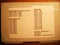
Also needs to note, that the typical passive twin T notch attenuation -9,1dB for the second H, and -5,1dB for the third H appears only in "ideal" condition, when the source impedance is "0" and no load at the notch output. In real conditions this attenuation will be higher. When the source impedance is 600 ohm, the attenuation would be app. -10,2dB for 2H, and -6,5dB for 3H.
Something else, if I may. I can't seem to get around using balanced cabling for spectrum analysis with lowest mains spurs.
But I also need to use my passive twin-tee to get to measure at the -150dB level.
So I need a balanced passive notch. Brute force would suggest a pair of passive notches, one in each balanced input line, but maybe there is a smarter way to do this? Google is no help here.
Jan
Actually a no-brainer ...
Nice thing is that now all R's are identical, all C's are identical.
Jan
Attachments
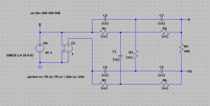
I can recommend to build two identical classical notches. If you already have one ready, then needs to build one similar else. Then you can measure any signal - balanced or unbalanced. Otherwise may be some limitations for balanced twin T without the GND point.Actually a no-brainer ...
Nice thing is that now all R's are identical, all C's are identical.
Jan
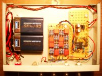
I have a good single-ended one, I will build another balanced, the cost is very reasonable, especially now that Rs and Cs are equal.
The single ended one is in a small aluminum case and that also picks up some mains spurs.
For the balanced I will see if I can get a brass or steel enclosure. Will visit the local Home Depot tomorrow ;-)
Also want to include a bypass switch, I really feel that I miss that in the single ended one.
Jan
Actually a no-brainer ...
Nice thing is that now all R's are identical, all C's are identical.
Jan
Cool!
I've been pondering a question about passive vs. active twin T notch. It seems we usually assume that a passive one has lower distortion and we just put up with the H2 and H3 loss errors. But is the passive really lower in distortion than an active in the scenarios where we use it to notch out a fundamental for measurement purposes?
In these scenarios, if we are getting a notch of 40 dB or more, the amplitude of the signal being processed by the amplifier following the twin T and providing the active feedback is very small - that amplifier is really just processing the distortion products plus a very small amount of fundamental leakage. That amplifier will usually necessarily be operating in non-inverting mode, so it will be subject to common-mode input, but, once again, the common-mode signal is very small.
There is one caveat to this, however, which might be the source of possibly increased distortion compared to the passive design. That is that the amplifier must handle some signal current from the twin T network that it is feeding back to. I suppose that current could cause some distortion in the output stage. The passive notch enjoys the fact that the network node we are talking about goes directly to ground through no impedance. In the active design, that node sees the closed-loop output impedance of the amplifier. It is also fair to note that this impedance will be quite a bit higher at 20 Khz than at the 1 kHz we are frequently talking about.
Cheers,
Bob
You are right about the cables, in the sense that I couldn't get the mains low enough using single ended coax cables.
But as soon as I used balanced cables, the mains stuff went down to the AP with shorted input. Of course, CMRR at 50Hz is very high.
I hear you on the brass. I'll see if I can get some brass fittings at Home Depot large enough to house a small PCB, with end caps for the XLRs. Steampunk I say!
Jan
But as soon as I used balanced cables, the mains stuff went down to the AP with shorted input. Of course, CMRR at 50Hz is very high.
I hear you on the brass. I'll see if I can get some brass fittings at Home Depot large enough to house a small PCB, with end caps for the XLRs. Steampunk I say!
Jan
yep.Ralf this is two single ended, correct?
Jan
There is one caveat to this, however, which might be the source of possibly increased distortion compared to the passive design. That is that the amplifier must handle some signal current from the twin T network that it is feeding back to. I suppose that current could cause some distortion in the output stage. The passive notch enjoys the fact that the network node we are talking about goes directly to ground through no impedance. In the active design, that node sees the closed-loop output impedance of the amplifier. It is also fair to note that this impedance will be quite a bit higher at 20 Khz than at the 1 kHz we are frequently talking about.
Cheers,
Bob
In my work for the tracking notch, I found that at the levels of distortion we are talking about here, -140dB or below, any capacitive load on an opamp immediately is visible in the distortion. It doesn't impact stability, and apparently everything is fine, but the distortion gets up fast.
Using some series R on the opamp output improves it of course. But it impacts the notch depth. It's a fine balance of getting the distortion extremely low and still getting a notch depth of at least 40dB.
I would expect, but haven't tested, similar issues to manifest themselves with the active twin-t.
Jan
There are two disadvantages else in the case of "balanced passive twin T" vs two unbalanced when they used as balanced:I have a good single-ended one, I will build another balanced, the cost is very reasonable, especially now that Rs and Cs are equal.
Jan
1) the voltage across the common capacitor will be two times higher, so may more distort.
2) if the alternate signals in line will be not absolutely equal in amplitude, you will get unwanted common mode voltage at output.
- Home
- Design & Build
- Equipment & Tools
- Low-distortion Audio-range Oscillator