From my tests and from the reports of other people measuring capacitor problems, one constant that can be stated is that, regardless of the absolute performance level of a capacitor dielectric type, wound film capacitors will exhibit a wide variation of distortion behaviors, and I would like to characterize this as a result of the unit by unit success or failure of electrode termination in each device.
Of course, different manufacturers will have different processes that will have better or worse success in preventing distortion from electrode termination problems, but in aggregate, it's a crap shoot to rely on any manufacturer and any specific process or dielectric choice to mitigate this issue.
At the same time, I have also found that C0G dielectric monolithic multilayer capacitors do not exhibit these sorts of distortion problems. Their distortion seems to be very well characterized unit to unit, unlike the situation with wound film capacitors. They will exhibit distortion according to the voltage gradient placed across the dielectric, but this distortion will be very consistent from unit to unit.
So, my recommendation is that, if you want a consistent, low distortion capacitor, a high quality C0G/NP0 MLCC is the best plan, choosing the physically largest capacitor with the highest voltage rating possible.
Hi,Yes, the capacitors test is not so easy. Also the different results may appear at different frequencies, signal levels and from piece to piece. Every example must be individually tested when needs to use it in a sensitive place.
Some of us are equipped with old 3rd DI analyzer, like the CLT form Danbridge. If I may help we can discuss capacitor distortion index or you can send sample I will qualify.
Regards,
Pierre
Hi Pierre,
Thank you. CLT form Danbridge is the really great tool. If I properly understand, it can see -160dB third harmonic @10kHz. But would be interesting to see deeper at different frequencies. This tool can see only the third harmonic, but the second is also important. I can see similar levels @1kHz 2,7 V RMS. Some measurements of 10nF 1206 COG and Wima FKP2 capacitors was posted in this thread:
Low-distortion Audio-range Oscillator
Hi Pierre,
Thank you. CLT form Danbridge is the really great tool. If I properly understand, it can see -160dB third harmonic @10kHz. But would be interesting to see deeper at different frequencies. This tool can see only the third harmonic, but the second is also important. I can see similar levels @1kHz 2,7 V RMS. Some measurements of 10nF 1206 COG and Wima FKP2 capacitors was posted in this thread:
Low-distortion Audio-range Oscillator
I have two of them. Fixed frequency at 10 KHz fundamental. Its designed to readout the 3rd harmonic since that's the most sensitive for construction variables and reliability. Mine both do go down to -170 with no load.
I have 2 so I can test pots. Most pots are pretty bad. The Japanese and the Bourns seem OK.
You can connect a spectrum analyzer (or a sound card at 192 KHz) to the monitor output for a full spectrum. 2nd is not as low but 4th may be a good proxy for 2nd harmonic issues. The test has the cap under real stress if done right with the harmonics unloaded so its very sensitive.
Once set up screening can be done pretty quickly.
I'm learning a lot reading through this thread. The solder mask clue is really a thinker. I remember back in day having high humid/moisture issues on some ad boards in 80s. I had forgotten that. Doing hi-z inverted triode fun now and will leave opamp-fb-valve no solder mask. That's a really good idea. And too moisture is never trapped in like Si conformal coatings. They absorb 2-3% by weight water normally. On the oscillator, maybe leave entire solder mask off and run tests baking inside mini oven set for 110f, bimetal control, no electronics. Good shield too? The two-and-half sided board going to be used too. I received the Hk osc board but no time to test now.
Attachments
Aaaaand.... i knew it. I shouldn't havesaid thatlurked here.
Now i want to implement ADC with sample rate lock on measured carrier signal. Problem solved!
It should be easy... i guess.
First of all, it wasn't THAT easy...
Second, it actually works
")
Phase locking of analyzer sampling to measured carrier, reduces phase noise, eliminates wander and scalloping (if locked to bin-centre frequency).
Signals are synthetic, sine wave + phase noise + distortion. the "999.99Hz" are "PLL locked", "1078Hz" aren't.
The grand scheme of things:
ASRC: x32 upsampling by zero-stuffing, convolution by Sinc-windowed-by-Kaiser-9, and then interpolating between samples by quadratic interpolation.
Then i feed the ASRC with frequency difference data (zero-crossing detector with a bit of interpolation Vs target 1kHz frequency) and then... Magic!
I still need to fix interpolation at zero-detector (running linear and unhappy), as well as figure out the control of PLL corner frequencies.
Attachments
First of all, it wasn't THAT easy...
Second, it actually works
Interesting, I was originally thinking injection locking of the oscillator with one channel and measuring with the other so no windowing.
Great! I just ordered a bunch of boards at Seeed. Delivery 2-3 weeks.
Anyone want one? $2 + shipping (letter) at cost.
If LKA is OK with that, of course. LKA, if you want some, let me know, my gift back to you.
Jan
Hi jan, could you kindly put me down for 4 boards please and PM with how you want to be paid.
Best regards
Mike
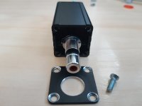
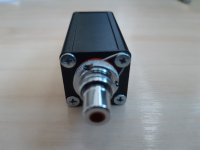
You should buy box made of natural aluminium.
one issue with painted box : shielding doesn't work well
workaround
- scrape off the paint under the screws
- use unpainted screws
- make connection betwen screw and RCA on one end
Attachments
You should buy box made of natural aluminium.
one issue with painted box : shielding doesn't work well
workaround
- scrape off the paint under the screws
- use unpainted screws
- make connection betwen screw and RCA on one end
Yes, clear.
Jan
Hi Jan,
Please 2 PCB for me too.
Thanks and best regards
Noted.
Jan
Hope we can conclude this before Brexit
What is a Brexit?
Pierre
Great! I just ordered a bunch of boards at Seeed. Delivery 2-3 weeks.
Anyone want one? $2 + shipping (letter) at cost.
If LKA is OK with that, of course. LKA, if you want some, let me know, my gift back to you.
Jan
Gone. Three people have signed up. I have will have 2 boards available for each of you, sorry not 4. I will PM you when I get them.
Jan
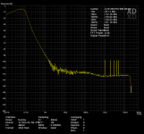
Made some progress today with proto#2 of my auto-tracking active notch.
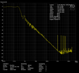
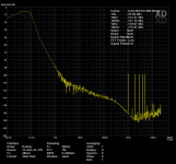
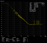
The attached shows the result from a rainy Sunday.
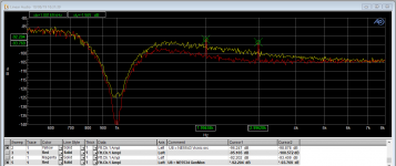
The yellow trace is the output of the 1kHz notch, input is Viktor's 1kHz oscillator. The notch dept is about 44dB, and there is no distortion visible. The noise floor at 2kHz is ~-138dB and at 3kHz ~-144dB.
The red trace is with the AP generator as input. Here we clearly see the residual of the AP generator, at ~-136dB and 3rd at ~-138dB.
If I do a loopback I get these same numbers for the AP. So the concept seems to work and I can already show that Victor's oscillator is better than the AP.
I am not sure what I am seeing re: noise floor. The measurement with the AP generator has a lower noise floor, so the relatively high noise floor of the yellow Viktor curve seems to indicate that the Viktor measurement is limited by its noise.
Viktor always shows lower noise which might be due to the fact that he uses a much smaller bin width than the AP.
Viktor, Demian, others, do you have any comments/hints on this?
Jan
The attached shows the result from a rainy Sunday.
The yellow trace is the output of the 1kHz notch, input is Viktor's 1kHz oscillator. The notch dept is about 44dB, and there is no distortion visible. The noise floor at 2kHz is ~-138dB and at 3kHz ~-144dB.
The red trace is with the AP generator as input. Here we clearly see the residual of the AP generator, at ~-136dB and 3rd at ~-138dB.
If I do a loopback I get these same numbers for the AP. So the concept seems to work and I can already show that Victor's oscillator is better than the AP.
I am not sure what I am seeing re: noise floor. The measurement with the AP generator has a lower noise floor, so the relatively high noise floor of the yellow Viktor curve seems to indicate that the Viktor measurement is limited by its noise.
Viktor always shows lower noise which might be due to the fact that he uses a much smaller bin width than the AP.
Viktor, Demian, others, do you have any comments/hints on this?
Jan
Attachments
That looks like what I see with both active notches and the Shibasoku. The noise in Victor's oscillator can be defined by the impedances in the circuit, including the output resistor. I have noticed the KH4400 with its 50 Ohm output has a distinctly lower noise floor as well. Also near resonance the resistance changes and that accounts for some of the noise increase both in the oscillator and especially in the notch. When looking that low I increase the FFT resolution just to get lower. Usually 7 averages of a 5 million point FFT. It can take 1/2 hour to capture but you can see very deep. I don't think the AP supports that.
With the notch and DiANA's latest upgrade you should be able to cross-check your measurements with a more conventional sound card.
When the harmonics get that low (-140 dB+) you cannot be certain who is contributing. Both the interactions of the phases and amplitudes and the nonlinearities of the parts themselves can be an issue. You might try my trick of a low pass filter on the output of the oscillator to see if the change in harmonic level tracks or shifts. This would be an indication of cancellation or real harmonics. Pavel is using that in his distortion cancellation method.
Harmonics this low are in the time-nut and volt-nut realm. Way below anything with real world impact for us (unless you are building your own LIGO?) but an interesting pursuit anyway.
Somebody send me this quote:
If you think getting below -100dB is challenging, things become even "weirder" down below -120dB. At -140dB you must question almost every component in your circuit, and even then, getting repeatable results often depends upon the phase of the moon."
--Bruce Hofer, Audio Precision
I'm running a 4M points, 16 averages FFT right now.
Jan
- Home
- Design & Build
- Equipment & Tools
- Low-distortion Audio-range Oscillator