Richard I didn't get before measurements for comparison. Can you take some measurement spectrum of the 339A and post it for comparison?
OK. Soon.
-RNM

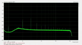
Stock osc at osc output.
[no mods just cal trim adj]

It is about 10dB worse plus 5th
Only difference is mod unit above had changed osc OPA and buffer OPA and added trim adj of jFET.
Noise also matters ... especially in THD+N tests. The lowered osc. noise allows the analyzer to go to read the actual -105dB THD+N as -102dB. But, with a cleaned up analyzer also (lower noise OPA's) the true THD+N of -105dB is seen. This is as low as this analyzer can measure. [stock osc+analyzer reading is noise limited to about -95dB]
.

THx-RNMarsh
[no mods just cal trim adj]
It is about 10dB worse plus 5th
Only difference is mod unit above had changed osc OPA and buffer OPA and added trim adj of jFET.
Noise also matters ... especially in THD+N tests. The lowered osc. noise allows the analyzer to go to read the actual -105dB THD+N as -102dB. But, with a cleaned up analyzer also (lower noise OPA's) the true THD+N of -105dB is seen. This is as low as this analyzer can measure. [stock osc+analyzer reading is noise limited to about -95dB]
.
THx-RNMarsh
Last edited:

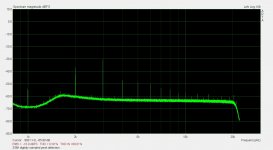
Right at the level control on the osc opa output........ HP-339A stock osc parts:
View attachment 529029
THx-RNMarsh
You have a 120Hz modulation showing in the spectrum by the side bands on each side the of the fundamental and the harmonics to a lesser degree.
Is the level higher here than with the first two pics. Why is the distortion higher?
You have a 120Hz modulation showing in the spectrum by the side bands on each side the of the fundamental and the harmonics to a lesser degree.
Is the level higher here than with the first two pics. Why is the distortion higher?
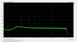
The ground point used wasnt the best.
It is a stock unit.
Level is much higher as shown by peak levels of 1KHz fundamental signal.
THx-RNMarsh
The ground point used wasnt the best.
It is a stock unit.
Level is much higher as shown by peak levels of 1KHz fundamental signal.
I still use my HP 339A religiously. Excellent ULDO, all around, and still commonly found on ebay, et al, for reasonable prices.
THx-RNMarsh
BTW --- often the plastic dials on the front panel knobs get broken after time. Do you or anyone else know where to get new replacements (NOS is OK).
THx-RNM
Bold statement. There are no replacement HP knobs available for the 339A. I looked.
As far as I know they are all broken. There is an industrial knob available in the same shape which is labeled with numbers. They are not clear plastic though. Solid aluminum. I'm not sure the numbers will line up with the detent, The shaft size is also a challenge.
If there is a knob that will fit, one could put the numbers on manually. But what a job.

Peak detector ripple and effect on oscillator distortion
There has been some discussion over the past few years whether peak detector ripple adds to oscillator distortion. There has been opposing views on the subject.
I've seen the effect in spice but have never tested to verify the effect. With a bit of nudging from Richard March I decided to do a study on the 339A oscillator.
I built a version of my digital multiplier on a PCB of it's own. The multiplier is a 16 bit ADC and 16 Bit Mdac (Multiplying DAC). Besides functioning as an digitally controlled analog multiplier it also functions a sampled peak detector. The Mdac can hold a peak value indefinitely in it's register or until another peak value replaces it. There is no droop with this type of peak detector and thus no ripple at the output.
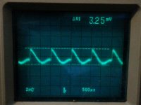
Bellow are pics of an AB comparison of the 339A oscillator with it's conventional diode, capacitor and pull down resistor type peak detector and the digitally sampled peak detector. The diode in the 339A peak detector is lifted and the sampler is inserted in its place. I've also included an oscillogram of the ripple at the output of the level controller. With the sampler inserted the ripple is gone with nothing but a flat line and high frequency noise on the scope.
Additionally, I reconnected the diode and inserted the sampler between the controller output and Jfet gate resistor. In this case the sampler functions as a perfect ripple filter which outputs a clean dc control signal.
There is some evidence my cat has been playing with my scope.
The measurement is done on a Shibasoku 725D in the -100dBV range.The scale is -100dBV for 0dBV on the plot.
Subtract 100dB from the reading.
There has been some discussion over the past few years whether peak detector ripple adds to oscillator distortion. There has been opposing views on the subject.
I've seen the effect in spice but have never tested to verify the effect. With a bit of nudging from Richard March I decided to do a study on the 339A oscillator.
I built a version of my digital multiplier on a PCB of it's own. The multiplier is a 16 bit ADC and 16 Bit Mdac (Multiplying DAC). Besides functioning as an digitally controlled analog multiplier it also functions a sampled peak detector. The Mdac can hold a peak value indefinitely in it's register or until another peak value replaces it. There is no droop with this type of peak detector and thus no ripple at the output.
Bellow are pics of an AB comparison of the 339A oscillator with it's conventional diode, capacitor and pull down resistor type peak detector and the digitally sampled peak detector. The diode in the 339A peak detector is lifted and the sampler is inserted in its place. I've also included an oscillogram of the ripple at the output of the level controller. With the sampler inserted the ripple is gone with nothing but a flat line and high frequency noise on the scope.
Additionally, I reconnected the diode and inserted the sampler between the controller output and Jfet gate resistor. In this case the sampler functions as a perfect ripple filter which outputs a clean dc control signal.
There is some evidence my cat has been playing with my scope.
The measurement is done on a Shibasoku 725D in the -100dBV range.The scale is -100dBV for 0dBV on the plot.
Subtract 100dB from the reading.
Attachments
Last edited:
There has been some discussion over the past few years whether peak detector ripple adds to oscillator distortion. There has been opposing views on the subject.
I've seen the effect in spice but have never tested to verify the effect. With a bit of nudging from Richard March I decided to do a study on the 339A oscillator.
I built a version of my digital multiplier on a PCB of it's own. The multiplier is a 16 bit ADC and 16 Bit Mdac (Multiplying DAC). Besides functioning as an digitally controlled analog multiplier it also functions a sampled peak detector. The Mdac can hold a peak value indefinitely in it's register or until another peak value replaces it. There is no droop with this type of peak detector and thus no ripple at the output.
Bellow are pics of an AB comparison of the 339A oscillator with it's conventional diode, capacitor and pull down resistor type peak detector and the digitally sampled peak detector. The diode in the 339A peak detector is lifted and the sampler is inserted in its place. I've also included an oscillogram of the ripple at the output of the level controller. With the sampler inserted the ripple is gone with nothing but a flat line and high frequency noise on the scope.
Additionally, I reconnected the diode and inserted the sampler between the controller output and Jfet gate resistor. In this case the sampler functions as a perfect ripple filter which outputs a clean dc control signal.
There is some evidence my cat has been playing with my scope.
The measurement is done on a Shibasoku 725D in the -100dBV range.The scale is -100dBV for 0dBV on the plot.
Subtract 100dB from the reading.
Nice work! How is this different from using an analog sample-hold as the agc detector?
We always need to bear in mind and understand which source of distortion in an oscillator, the agc ripple or the distortion of the agc element, is the largest contributor to distortion. Of course, I am guessing they are both quite small here.
Cheers,
Bob
If there is a knob that will fit, one could put the numbers on manually. But what a job.
you could have a new skirt made with 3d printer.
Hi Bob,
The analog THSH (track and hold sample and hold) Samuel designed reportedly has 12uV of ripple. I don't think 12uV will have any impact at all. So if an THSH is well designed it should do.
I made a PCB for the multiplier so I could test it on other oscillator types besides the variable state. I will have some data posted on replacing the Jfet in 339A with the digital multiplier.
Should be interesting.
Hi Bob,
The analog THSH (track and hold sample and hold) Samuel designed reportedly has 12uV of ripple. I don't think 12uV will have any impact at all. So if an THSH is well designed it should do.
I made a PCB for the multiplier so I could test it on other oscillator types besides the variable state. I will have some data posted on replacing the Jfet in 339A with the digital multiplier.
Should be interesting.
Thanks, David.
Could you describe the arrangement you had in mind to achieve 256 steps of resistance with 8 relays? Are the spst, spdt or dpdt?
Cheers,
Bob
One problem that's been sighted with trimming the feedback ratio around the Jfet by trimming one of the resistor is that it's specific to one frequency. If we tweak the ratio of these resistors at 1KHz it is not right for 10kHz. This effect shows up with the 339A oscillator.
Substituting the Jfet with the digital multiplier eliminates the need for trimming. Using a sampling multiplier means the ripple at the controller output will be eliminated. it does this because the ripple is sampled at exactly the same phase on each oscillator cycle.
The multiplier can use the existing controller with a bit of tweaking of the controller time constants.
Thanks, David.
Could you describe the arrangement you had in mind to achieve 256 steps of resistance with 8 relays? Are the spst, spdt or dpdt?
Cheers,
Bob
Did I post this in the wrong thread? It was supposed to be in Another Realization ....
I find the link.
One problem that's been sighted with trimming the feedback ratio around the Jfet by trimming one of the resistor is that it's specific to one frequency. If we tweak the ratio of these resistors at 1KHz it is not right for 10kHz. This effect shows up with the 339A oscillator.
Substituting the Jfet with the digital multiplier eliminates the need for trimming. Using a sampling multiplier means the ripple at the controller output will be eliminated. it does this because the ripple is sampled at exactly the same phase on each oscillator cycle.
The multiplier can use the existing controller with a bit of tweaking of the controller time constants.
This is an interesting observation. I have not seen this phenomenon on my THD analyzer, but have not looked hard for it. What is the underlying theory as to why there should be a frequency dependence of the optimum JFET feedback ratio?
Cheers,
Bob
This is an interesting observation. I have not seen this phenomenon on my THD analyzer, but have not looked hard for it. What is the underlying theory as to why there should be a frequency dependence of the optimum JFET feedback ratio?
Cheers,
Bob
I suspect that there is also some distortion canceling going on with the 339A. But this is just speculation and is very difficult if not impossible to prove. I have no test for it. So it remais just an observation.
Your use of a Jfet in you multiplier is quite different to how the Jfet is used in the 339A. In the 339A it is just a shunt to ground of the positive feedback. The feedback is a resistor from output to the non inverting input of the oscillator op amp U1. Much simpler than your multiplier.
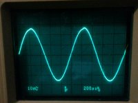
The oscillator runs at 20mVpp.
Here is pic of the voltage at the Jfet drain. It's about 52mVpp.
You can see the distortion from the peak detector ripple on the positive peaks of the sine.
Oops that is the gate.
Here is one of the drain and another at the input to the op amp.
This is very high level compared to an SVO. The peak gain at resonance is not nearly as high with a bridged T as it is with an SVO.
Attachments
Last edited:
- Home
- Design & Build
- Equipment & Tools
- Low-distortion Audio-range Oscillator