Richard:
Your AP is reading substantially better than Samuel s. The 160 dB notch looks unreal. I could see maybe as much as 5 dB difference but 10-20?
Samuel:
Do the ESS DAC's actually deliver the claimed distortion? ESS told me that the layout of the digital side is very critical. It seems getting the results possible can be quite difficult. Do you have experience with the ESS ADC? I have seen no real reports on the part yet.
On a separate but related thread element the Krohn Hite 4000 series oscillators offered very low frequencies with very low distortion. I used to have some. I still have the manual and could scan the key parts if you are interested. The sample and hold they used worked well but you could see it's glitch in the distortion output.
Your AP is reading substantially better than Samuel s. The 160 dB notch looks unreal. I could see maybe as much as 5 dB difference but 10-20?
Maybe such a huge difference is due to higher input level (20 dBu vs 0 dBV) in Samuel's test? Nevertheless a 160 dB deep notch is amazing, even for a two stage-notch.
L.
The achieved notch cannot be lower than the noise floor (-155dB) in principle. There should be a certain signal above this floor to make the notch filter tunable. The closer this floor, the harder is to reach a further notch, I know this very well in practice (VK-2 distortion meter).Richard:
Your AP is reading substantially better than Samuel s. The 160 dB notch looks unreal. I could see maybe as much as 5 dB difference but 10-20?
So about 250v ... that would do just fine
We clearly need just a few more bits... 2-4? --- more head room ... and then not need a notch filter.
I'm dreaming. Right?
-RNM
I think the problem will be the needed resistor precision for the conversion.
Not to mention the oscillator precision. Actually the state of the are would be this: Superconducting JJ-Array IC | Voltage Standard | Superconducting Integrated Circuit | Hypres Inc. good to .005 ppm accuracy but only 20,208 steps from 0 to 10V. And the operating budget would strain even the most extravagant audiophile. However using liquid Helium would bring certain bragging rights.
I have been thinking about how to verify such low distortion numbers. I believe the best way would be to add a marker tone at a level close to the distortion product and not harmonically related at the input to the analyzer. The challenge is how to do it.
I came up with this idea- using a bnc to bnc cable for the input is standard practice. If we add a current to the shield that would generate a voltage drop it would be in series with the source and show pretty reliably. The cable shield is likely to be on the order of 20-100 mOhms so a divider that can correctly divide about -120 dB into 100 mOhms is the next challenge. That will prove harder than it looks. More on this as I experiment.
I came up with this idea- using a bnc to bnc cable for the input is standard practice. If we add a current to the shield that would generate a voltage drop it would be in series with the source and show pretty reliably. The cable shield is likely to be on the order of 20-100 mOhms so a divider that can correctly divide about -120 dB into 100 mOhms is the next challenge. That will prove harder than it looks. More on this as I experiment.
Standards to compare against -
Reminder -- specs are not viewed as the limit of a professional instrument but its guaranteed minimum. Samual's may be within spec -- However, it might not be. From B.Hofers papers showing 2722 data/measurements.... the suppression of the fundamental is often seen as -150dB in the figures of the literature from 2003.
Seems to me that in THD+N measurements, the fundamental needs to be down to the analyzer noise floor in order to Not be included in the measurement total. ?
"...... However, THD measurements are less sensitive to noise than THD+N measurements and thus, advantageous at low signal levels. However, THD+N still affords the lowest residual distortion performance because the analog notch filter effectively removes the ADC contribution."
As everyone told me before. And A-P says 100dB is about the limit direct into their 24bit ADC. Maybe -110dB. Also, as I found, maybe even less with QA400. I'm just plodding along until I feel everything is thoroughly gone thru and understood before I can say what is what when testing. Not just being a button pusher.
And, when direct into the 2722, B.Hofer shows us the result is extraneous freqs are produced... just like I/we get. Of course the AP has a built in notch. The sound-card types and the QA400 etal do not... unfortunately. And, there are several people here and elsewhere who have used notch filters for some time with less expensive ADC/FFT based systems.
That's the final step.... now that I have a couple references to compare against --- using an added notch filter, how well does the QA400 do? Or, an eMu product? Accuracy and at low levels of distortion? How accurate and how low? I hope that it does very well and is accurate enough at low enough levels for everyone to use with confidence. And with the knowledge of its particular limitations and what they are when measuring our oscillator/generators or audio amplifiers.
Thx-RNMarsh
The notched fundamental doesn't bother me at -155-158dB as indicated. The harmonics being measured are the same level [within 1dB] of those of the ShibaSoku.
Thx-RNMarsh
Reminder -- specs are not viewed as the limit of a professional instrument but its guaranteed minimum. Samual's may be within spec -- However, it might not be. From B.Hofers papers showing 2722 data/measurements.... the suppression of the fundamental is often seen as -150dB in the figures of the literature from 2003.
Seems to me that in THD+N measurements, the fundamental needs to be down to the analyzer noise floor in order to Not be included in the measurement total. ?
"...... However, THD measurements are less sensitive to noise than THD+N measurements and thus, advantageous at low signal levels. However, THD+N still affords the lowest residual distortion performance because the analog notch filter effectively removes the ADC contribution."
As everyone told me before. And A-P says 100dB is about the limit direct into their 24bit ADC. Maybe -110dB. Also, as I found, maybe even less with QA400. I'm just plodding along until I feel everything is thoroughly gone thru and understood before I can say what is what when testing. Not just being a button pusher.
And, when direct into the 2722, B.Hofer shows us the result is extraneous freqs are produced... just like I/we get. Of course the AP has a built in notch. The sound-card types and the QA400 etal do not... unfortunately. And, there are several people here and elsewhere who have used notch filters for some time with less expensive ADC/FFT based systems.
That's the final step.... now that I have a couple references to compare against --- using an added notch filter, how well does the QA400 do? Or, an eMu product? Accuracy and at low levels of distortion? How accurate and how low? I hope that it does very well and is accurate enough at low enough levels for everyone to use with confidence. And with the knowledge of its particular limitations and what they are when measuring our oscillator/generators or audio amplifiers.
Thx-RNMarsh
Last edited:
I verified the concept of using a voltage drop across the BNC cable as a form of insert calibration. I'll need to go through some more precise steps to turn it into something reproducible. It does enable verification of everything from attenuation of harmonics to really low harmonic levels. What I need to do is check several coaxes to determine which is most predictable for this.
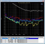
A too deep notch can also produce additional errors with rather crude (18 Bit, Successive approximation ??) A/D converters as the one used in the SYS-2722, which seem to have a rather bad fade to noise linearity and thus need a certain fundamental magnitude in order to achieve the best dynamic range.
This effect you can see in the appended plot of my SYS-2722, which shows the H2...H5 fundamental residuals for 20kHz at different levels. Especially at very low levels below 80mV (where the instrument stops switching attenuators in the analyzer and thus runs more and more into linearity problems due to dropping level into the A/D converter ...).
In order to see this effect, the noise floor had to be lowered by roughly 55dB below the THD+N at the used 500kHz BW.
The sweep of 100 heavily averaged synced FFTs ran a few hours, but gives some new insight.
Even Mr. Hofer seemed to be a little surprised, when he first saw my plots, which seem to be quite revealing ...
Its probably like electron microscopes, which open up a very very weird world ...
This instrument should nevertheless perform very well in comparison to other off the shelf instruments of recent production, since it is one of the very few instruments, which are hand tweaked for low THD20k by Bruce Hofer's golden hands, for which I thank him twice a week ...
Attachments
I verified the concept of using a voltage drop across the BNC cable as a form of insert calibration. I'll need to go through some more precise steps to turn it into something reproducible. It does enable verification of everything from attenuation of harmonics to really low harmonic levels. What I need to do is check several coaxes to determine which is most predictable for this.

new tests -- using 2722
 Jon Lord --- I was wondering in the past few days after looking at the A-P working.... don't we trade off the high level input non-linearity for low level non-linearity of the ADC? The 18 bit -- is that the sample and hold? The data you show indicates a 10dB average variation at those low levels. Good to know.
That is so Very test data -- quite creative to look into this with a fresh new view or angle -- two thumbs up for you at KLN. Tell us more, please. Especially about the affects of the notch?
Thx-RNMarsh
Jon Lord --- I was wondering in the past few days after looking at the A-P working.... don't we trade off the high level input non-linearity for low level non-linearity of the ADC? The 18 bit -- is that the sample and hold? The data you show indicates a 10dB average variation at those low levels. Good to know. That is so Very
test data -- quite creative to look into this with a fresh new view or angle -- two thumbs up for you at KLN. Tell us more, please. Especially about the affects of the notch? Thx-RNMarsh
Last edited:
Here is some new data from the A-P 2722. It shows the internal limit of the A-P (2H and 3H are less than -145 dB).
Now we're getting somewhere
. Just don't make the mistake to believe that you could accurately measure down to -140 dB H2/H3 with your unit--you can't. Very likely you're seeing cancellation between generator and analyzer.Your AP is reading substantially better than Samuel's. The 160 dB notch looks unreal. I could see maybe as much as 5 dB difference but 10-20?
Maybe such a huge difference is due to higher input level (20 dBu vs 0 dBV) in Samuel's test? Nevertheless a 160 dB deep notch is amazing, even for a two stage-notch.
Rick notes that his unit has recently been calibrated, and I have a faint feeling that I've seen better notch depths after calibration (a few years back) too. Notch depth is probably mostly affected by offsets in the phase-sensitive detectors of the auto-tuning circuitry, and these might be subject to adjustment in the calibration process. In any case, notch depth is of no relevance once low enough to no affect a THD+N measurement.
The achieved notch cannot be lower than the noise floor (-155 dB) in principle. There should be a certain signal above this floor to make the notch filter tunable. The closer this floor, the harder is to reach a further notch, I know this very well in practice (VK-2 distortion meter).
I don't follow--can you elaborate? Surely the input signal needs to be sufficiently high above the noise floor for the auto-tuning to work well, but I'm not aware of fundamental notch depth limitations. Note that the -155 dB figure is not a noise measurement in a known equivalent noise bandwidth (e.g. changes with FFT parameters) and thus not suitable to define any hard limits.
I have been thinking about how to verify such low distortion numbers. I believe the best way would be to add a marker tone at a level close to the distortion product and not harmonically related at the input to the analyzer. The challenge is how to do it.
Can you elaborate why amplitude accuracy should be a particular problem? As far as my humble opinion goes, ensuring low distortion contribution from the notch appears to be far more challenging.
Seems to me that in THD+N measurements, the fundamental needs to be down to the analyzer noise floor in order to Not be included in the measurement total?
Sure.
A too deep notch can also produce additional errors with rather crude (18 bit, successive approximation?) A/D converters as the one used in the SYS-2722, which seem to have a rather bad fade to noise linearity and thus need a certain fundamental magnitude in order to achieve the best dynamic range.
I presume you're referring to the "high BW" ADC of the SYS-2722?
Samuel
Can you elaborate why amplitude accuracy should be a particular problem? As far as my humble opinion goes, ensuring low distortion contribution from the notch appears to be far more challenging.
Samuel
In the case of the Shibasoku monitor out there are several upstream agc's. Also true for some other analyzers. This trick allows for verification of signal levels in operation without some complex resistor mixing scheme. It may also be useful to confirm whether a nonlinearity is affecting levels at the -120 dB level in the ADC. As for cancellation etc, it may prove useful for demonstrating the effect.
However using liquid Helium would bring certain bragging rights.
That's how you get those electrons to stop spinning.
Now we're getting somewhere
In any case, notch depth is of no relevance once low enough to no affect a THD+N measurement.
Samuel
I believe the 2H is always more susceptible but further out from the fundamental should be better.
The state of the tune of the notch would affect the 2H level due to phase changes - I see this with some drift affects in tune. Take me/us to the next level.
What is needed to measure at or below -140db with any reasonable degree of certainty?
For myself, having two different instruments (A-P and ShibaSoku) agree helps the confidence factor. One important spec from the Japanese mfr, which I appreciate, is a spec limit on accuracy of the 2H -- spec'ed as +/- 1dB over the range of measurement.
Thx-RNMarsh
Last edited:
You could make a passive low pass filter and verify that it reduces the second or third harmonic by a known amount (and doesn't create new harmonics of its own) and then see if the reported harmonics of the ultra low distortion source drop by the predicted amount. If they do then the analyzer isn't generating them. If not there is clearly interaction. A single pole filter should get 3-6 dB on the second and approx 12 dB on the third. A two pole filter (2R's and 2C's) should do more and be more obvious. You may be able to do this with the B&K passive notch in the passive mode.
The Shibasoku is unique among these analyzers with no servo tuning. On paper that should make for lower residual distortion.
What I see in audio ADC's suggests that the performance is quite linear up to about 3 dB of full scale, then some harmonics pop up. Going down the harmonic spectrum is pretty constant for the top 30-50dB. Below that the noise intrudes.
In a well executed ADC the spurious tones are way down. If they are not then there is probably a layout, clock, crosstalk or power supply problem. I would look at the clock first. The improvement on the AKD5394A board from improved clocking, using the existing clock generation and distribution, is really dramatic. Slapping a "better" oscillator on the board may not help if the power or grounding aren't really good to start with. The critical spec for one of the high speed ADC's is "spurious free dynamic range" (SFDR).
Last edited:
We used LN on the FET input detector for a one-off SEM (Scanning Electron Microscope) and I could clearly see molecules of the HE sample. Now That is quiet !
I was an undergrad slave to the Physics Dept. in my youth. Some Jesuit had it in his mind to make copper-gold alloys go through transition close to real zero.
What I see in audio ADC's suggests that the performance is quite linear up to about 3 dB of full scale, then some harmonics pop up. Going down the harmonic spectrum is pretty constant for the top 30-50dB. Below that the noise intrudes.
If you're looking at a signal of constant frequency (and its harmonics, spurs, whatever) wouldn't a 24 bit ADC oversampled and averaged 4*4*4 times give you over 160dB? In which case, what do I do with my SR785?
In which case, what do I do with my SR785?
Sell it to me cheap. . . ?
- Home
- Design & Build
- Equipment & Tools
- Low-distortion Audio-range Oscillator