The seller also indicated he was comtemplating posting the schematic here or on his ebay ad.
Encourage him. I'm interested, but would like to know what I'm getting first! Also to know what the power supply requirements are to achieve the stated performance level.
Note he has added: "Improved version of this generator is on sale now . I can not change title. Typical performance of this generator now is app. - 136dB (0.15ppm) level of second harmonic, and unmeasurable (at this time) level of third harmonic (=<-140dB)."
Terry
Last edited:
Hi to everyone.
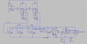
I am author of this generator from ebay. Thanks to all, who trust and buy this. I designed this generator especially for best performance/cost ratio. Cause of many people ask me abut schematic, then now I post it to this forum:
Symmetrized FET in AGC is the "heart" of this generator.
Improvement, which I made not long ago for better performance, is simple. I replaced all mean resistors in signal chain from 1206 Yageo cermet type to 0204 Vishay metal film. When I made 10kHz version, I observed some peculiarity in working, and in final I discovered, that resistors was not so good. And I was very impressed, when in 1kHz model distortions falls down after resistors replacement.
Excuse me, if there are some mistakes in my english.
Victor
I am author of this generator from ebay. Thanks to all, who trust and buy this. I designed this generator especially for best performance/cost ratio. Cause of many people ask me abut schematic, then now I post it to this forum:
An externally hosted image should be here but it was not working when we last tested it.
Symmetrized FET in AGC is the "heart" of this generator.
Improvement, which I made not long ago for better performance, is simple. I replaced all mean resistors in signal chain from 1206 Yageo cermet type to 0204 Vishay metal film. When I made 10kHz version, I observed some peculiarity in working, and in final I discovered, that resistors was not so good. And I was very impressed, when in 1kHz model distortions falls down after resistors replacement.
Excuse me, if there are some mistakes in my english.
Victor
Thanks very much for that, Victor. I'm sure it's giving many of us a lot to think about!
Incidentally, I realise you probably optimise the timing for each fixed frequency to get the best results, but have you tried your FET control approach in a variable frequency oscillator? Can you achieve lower distortion and less "bounce" than say a thermistor-controlled system?
Terry
Incidentally, I realise you probably optimise the timing for each fixed frequency to get the best results, but have you tried your FET control approach in a variable frequency oscillator? Can you achieve lower distortion and less "bounce" than say a thermistor-controlled system?
Terry
Victor, thank you!
Now i just had to pull the trigger on the 1kHz version. I guess i'll take the 10kHz version too, in the feature...
Aargh, i need to finish my ADC rig.
Should i run it on batteries, or plain transformer regulated supply would suffice?
Also thank you!
Plain transformer with simple regulated supply should be OK. I recommend transformer with windings in sections.
Thanks very much for that, Victor. I'm sure it's giving many of us a lot to think about!
Incidentally, I realise you probably optimise the timing for each fixed frequency to get the best results, but have you tried your FET control approach in a variable frequency oscillator? Can you achieve lower distortion and less "bounce" than say a thermistor-controlled system?
Terry
No one system is absolutely perfect, but if we have one target, we can optimize system for them. If we need to measure distortions, in my opinion, we not need do this in full frequency range, cause, that variable full range low distortions oscillator becomes very complicate and expensive. I think, we can measure distortions in some points with simple fixed frequency oscillators. Every AGC system also is not perfect. Thermistor make 3rd harmonic distortions, especially on low frequencies, have its own time constant, that we can not change and do not make good stability. I think, best simple solutin for AGC is optocoupler with photoresistor output, but it also have self nonlinear time constant and is not cheap.
Now FET controlled 1kHz oscillator have less than 0.3ppm distortions. I do not know at this time, which part of them makes measurable (app. - 136dB) 2nd harmonic, but once, may be I will find
")
No one system is absolutely perfect, but if we have one target, we can optimize system for them. If we need to measure distortions, in my opinion, we not need do this in full frequency range, cause, that variable full range low distortions oscillator becomes very complicate and expensive. I think, we can measure distortions in some points with simple fixed frequency oscillators.
Agreed, Victor. I'm looking forward to receiving one of your oscillators to be my primary distortion reference. I have a thermistor-style variable frequency oscillator and a function generator for other tests.
When I built my Noise and Distortion meter, I settled on three frequencies to avoid the complexity of full range tuning:
40Hz, being about the lowest musical notes likely to be encountered
400hz, being in the middle of the vocal and instrumental fundamentals range, and
4kHz, being about the top of the instrumental fundamentals range.
I didn't see much point in measuring harmonic distortion at 10kHz or so, as I was not going to hear even gross 2nd harmonic distortion at 20kHz, let alone 3rd at 30k. I'd be interested in comments on that strategy.
Terry
Hi Terry,
My vote is for 50Hz, 1kHz and 20kHz. Those are the frequencies used by many others, including John Atkinson of Stereophile. This allows you to make meaningful comparisons.
The chosen frequency for the mid-band is non-critical, and in this sense 400Hz and 1kHz are about equivalent.
50Hz and 40Hz should not give much different results. Many solid-state amplifiers don't do as well at 50Hz as one might expect, so the LF THD test is important. If looking at the spectrum of the residual, you can see any 60Hz components as well under these stressed conditions of medium to high power.
Many people dismiss 20kHz THD because they cannot hear any of the harmonics. But it is important to recognize that the THD-20 measurement is measuring a symptom of high-frequency nonlinearity. If THD-20 is not so good, there will surely be IM products reflected down into the audio band (look at 19+20kHz CCIF IM distortion spectra).
Cheers,
Bob
Agreed, Victor. I'm looking forward to receiving one of your oscillators to be my primary distortion reference. I have a thermistor-style variable frequency oscillator and a function generator for other tests.
When I built my Noise and Distortion meter, I settled on three frequencies to avoid the complexity of full range tuning:
40Hz, being about the lowest musical notes likely to be encountered
400hz, being in the middle of the vocal and instrumental fundamentals range, and
4kHz, being about the top of the instrumental fundamentals range.
I didn't see much point in measuring harmonic distortion at 10kHz or so, as I was not going to hear even gross 2nd harmonic distortion at 20kHz, let alone 3rd at 30k. I'd be interested in comments on that strategy.
Terry
Thank you, Terry.
1kHz oscillator already shipped to you.
About measuring. I think, that there are no limits for the audio equipment performance. Our ears are so magic tool. We can hear differences, that practically no one measurment tool can.
In measurment practice, I think, that more interesting and more informative are points on the audio range borders and middle point - app. 20Hz, 20kHz, 1kHz. Some combinations for the IMD testing are also interesting. Low frequency measuring is important for RIAA amplifiers and, in my opinion, for possible specific thermal distortions. I accept, that Bob said about 20kHz distortions.
Regards,
Victor
Bob, I used 40Hz rather than 50 Hz as 50Hz is our local power frequency and I wanted to be able to differentiate between the test note and hum. I agree that 40 or 50 Hz are likely to give the same LF results. Good bass measurement. And I agree 400 Hz and 1KHz are also going to give essentially the same results. Good midrange measurement.
I still have my doubts though about the significance of distortion measurements much above say 5000Hz. I'm clinging to the conservative view that if you can't hear the artefact, it doesn't matter, but I'm happy to have the view exploded. You mentioned:
"Many people dismiss 20kHz THD because they cannot hear any of the harmonics. But it is important to recognize that the THD-20 measurement is measuring a symptom of high-frequency nonlinearity. If THD-20 is not so good, there will surely be IM products reflected down into the audio band (look at 19+20kHz CCIF IM distortion spectra)."
But even if high frequency non-linearity were significant, wouldn't this require pretty high levels of content at these elevated frequencies to trigger audible amounts of the IM products? I'm unaware of any musical instruments with significant energy up there.
Terry
Fletcher and Rossing (the bible on musical instrument acoustics) cites a study by Luce & Clarke (1967) on the topic of Acoustic Spectra of brass instruments (p453). From the graph, the "cut-off frequency" of the trumpet played mezzo-forte (moderately loud) is about 1kHz. They give the roll-off above cut-off as 15 to 25dB/octave. They do say that when played louder, the slope above cutoff decreases, but don't give a figure. If we guessed at 10dB/octave, and counted four octaves up from 1k to 16k, we'd expect the energy to be 40dB down wrt the peak level in the musical range. So the question becomes, how bad would the IM distortion at 16kHz have to be that harmonics 40dB down would create intermodulation products at lower frequencies that could be heard over the infernal racket the trumpet player is making anyway!
I do like baroque trumpet in particular, so I'll be very pleased is someone can convince me the maths above do not stack up!
Incidentally, be aware that when musical scientists use the expression "cut-off frequency", they mean more like what we would call "turnover frequency" or "corner frequency". It's the start of the downhill slide, not some point down the slope. That's why there can still be substantial energy above that frequency.
Terry
Last edited:
Thank you, Terry.
1kHz oscillator already shipped to you.
Thanks Victor! Looking forward to having a "gold standard"!
About measuring. I think, that there are no limits for the audio equipment performance. Our ears are so magic tool. We can hear differences, that practically no one measurment tool can.
In measurment practice, I think, that more interesting and more informative are points on the audio range borders and middle point - app. 20Hz, 20kHz, 1kHz. Some combinations for the IMD testing are also interesting. Low frequency measuring is important for RIAA amplifiers and, in my opinion, for possible specific thermal distortions. I accept, that Bob said about 20kHz distortions.
I notice you offer oscillators at 1kHz and 10kHz, but not a low frequency. Or is that still to come?
I am a bit tempted to change my 40, 400, 4kHz but still not sure what to. It is an inconvenience not to have "plain vanilla" 1kHz available, so that's probably one point. 50Hz is ruled out as being our mains frequency, so maybe 20Hz makes the best sense. But at the high end, 10kHz because it's still clearly audible, 15kHz because it's on my limit of audibility, or 20k because of the intermod theory? Decisions, decisions!
Terry
I chose 3 specific frequencies for oscillators from Victor. My need is for testing audio ADC's so those were 997 Hz (to avoid any interaction with sample rate subharmonics and to test every bit level) 11.025 KHz (44.1 KHz/4) and 12 KHz (48KHz/4) which are commonly used for Jitter testing. I can also use those for IM testing.
I'll be battery powering them (3 12V NiMH batteries in series from eBay @ $8.00 ea + a 36 V charger for $15 I think and some current limiting resistors). I get the best results from the stacked shunt regulators by powering them from an LM317 set as a current source. Also short circuit proof.
For low frequencies the level detection and agc are difficult. I think the only way to get reasonably fast settling is a sample and hold solution. That's much easier to implement with a state variable oscillator (you have a zero crossing to exploit at every peak). I have done some work towards this if anyone wants to pursue it. The simulations are promising but they are not working circuits yet.
I notice you offer oscillators at 1kHz and 10kHz, but not a low frequency. Or is that still to come?
Terry
Is possible to build low frequency oscillators, but there are two reasons why I do not offer them. ( I have one 20Hz oscillator for myself):
1) Practically no one asked me about low frequency similar oscillators.
2) In this configuration low frequency oscillators become very inertial for any output level changes and have very big settling time after switching ON. My 20Hz oscillator have more than 5 minutes settling time after switching ON. This cause of big time constants in AGC.
But, I still thinking about it
Victor.
Fast settling oscillator
Here is the unfinished design for the fast settling state variable oscillator. It borrows the additional peak detecting ideas from Cordell's oscillator, adding more and uses a trick I have used making an LM339 work as a peak detector.
The LM339 is a fast comparator but internally its like an unfinished opamp with open collector outputs. It has the virtue of not going nuts when the output is in an odd state. By feeding back the output to the input as shown it works as a "perfect" rectifier. Being open collector we can wire or several outputs together as shown.
The next stage is borrowed from the Fluke 510A oscillator which is designed to have extremely stable output. The DC offset from R2 moves the peak negative voltage to 0V at the output of U5. U6 is a comparator that switches to turn on the sample and hold at the peak voltage. This is modeled in the LM339 rectifier sim attached.
I have not added a sample and hold (did not see one in the library) or the AGC. I think Victors AGC would be well suited to this.
Also not done are the frequency tuning, the startup circuit or some of the other details. I found Victors modules and did not need to finish it.
Attachments
Fletcher and Rossing (the bible on musical instrument acoustics) cites a study by Luce & Clarke (1967) on the topic of Acoustic Spectra of brass instruments (p453). From the graph, the "cut-off frequency" of the trumpet played mezzo-forte (moderately loud) is about 1kHz. They give the roll-off above cut-off as 15 to 25dB/octave. They do say that when played louder, the slope above cutoff decreases, but don't give a figure. If we guessed at 10dB/octave, and counted four octaves up from 1k to 16k, we'd expect the energy to be 40dB down wrt the peak level in the musical range. So the question becomes, how bad would the IM distortion at 16kHz have to be that harmonics 40dB down would create intermodulation products at lower frequencies that could be heard over the infernal racket the trumpet player is making anyway!
I do like baroque trumpet in particular, so I'll be very pleased is someone can convince me the maths above do not stack up!
Incidentally, be aware that when musical scientists use the expression "cut-off frequency", they mean more like what we would call "turnover frequency" or "corner frequency". It's the start of the downhill slide, not some point down the slope. That's why there can still be substantial energy above that frequency.
Terry
Still a good source for the spectral content of various instruments is:
There's life above 20 kilohertz! A survey of musical instrument spectra to 102.4 kHz
- Home
- Design & Build
- Equipment & Tools
- Low-distortion Audio-range Oscillator