I've built an active Twin-T filter that works pretty well in conjunction with a spectrum analyzer -- I use the software analyzer ARTA under CrossOver Mac on my hackintosh.
The details are here:
Active Twin-T filter
Nulls as low as -90dB are pretty easy to achieve, and -100dB or more can be obtained for a short time. Deep nulls are not needed, however, when used with a spectrum analyzer -- you're just getting the fundamental level down low enough that the analyzer's or PC's input circuits are comfortable with the level and its own distortion doesn't intrude; -60dB to -80dB works great.
Just been reading your web site... very nice work! Did you get any further with that HP based oscillator?
I fear you may have missed out on something very nice in the form of the Morrey modifications to the IG18 though")
I don't have an IG18 but built the Morrey version from scratch, with a few changes of my own such as the regulated PSU and using a home-made "LDR and LED in a tube" instead of the specified Vactrol part. This required some changes to other feedback resistor values etc.
It performs very well indeed. My homebrewed distortion meter has a noise floor of 0.0014% (on the lowest range of 0.01% FSD) and after very careful nulling of the meter this noise floor is unchanged by the output of the oscillator!
One can surmise then that the actual distortion must be considerably lower than the 0.0014% mark.
Tests using PC based analysis merely showed the specified 0.002% of the USB audio interface.
I fear you may have missed out on something very nice in the form of the Morrey modifications to the IG18 though
I don't have an IG18 but built the Morrey version from scratch, with a few changes of my own such as the regulated PSU and using a home-made "LDR and LED in a tube" instead of the specified Vactrol part. This required some changes to other feedback resistor values etc.
It performs very well indeed. My homebrewed distortion meter has a noise floor of 0.0014% (on the lowest range of 0.01% FSD) and after very careful nulling of the meter this noise floor is unchanged by the output of the oscillator!
One can surmise then that the actual distortion must be considerably lower than the 0.0014% mark.
Tests using PC based analysis merely showed the specified 0.002% of the USB audio interface.
@jez -- I was attracted to the Morrey mods when they first appeared, then the problem reports started to show up. I was a bit put off by the complexity, though, and so never built one. The mod of the IG-18 to the HP 239 circuit is on hold for the moment, waiting for further small mods to the discrete circuit in IG-18 #1.
Try using a notch filter between your Morrey and the PC spectrum analyzer -- even a passive one can give you a lot of info if you adjust the displayed levels of the harmonics for the attenuation factors of the filter. A passive Twin-T will attenuate the 2nd H by roughly 9dB and the 3rd by roughly 5dB.
Try using a notch filter between your Morrey and the PC spectrum analyzer -- even a passive one can give you a lot of info if you adjust the displayed levels of the harmonics for the attenuation factors of the filter. A passive Twin-T will attenuate the 2nd H by roughly 9dB and the 3rd by roughly 5dB.
Dick,
I've been building your twin t notch filter. I'm almost done. I was wondering about the user of the three 1k trimmers. How are they used in setting up the filter? Should I initially set them at mid point values?
I'll post build photos next week (going out of town for the weekend). Hopefully it starts up and runs right off the bat. I enjoy reading your web entries and your re-greening projects.
Regards,
Ken
This may turn out to be a duplicate post -- if so, sorry
@jez -- Sorry I didn't see your note -- I don't remember well what I read about the problems in AA, but I think they mainly had to do with stability issues.
@klewis -- I look forward to seeing your build. I initially set the three 1k trimmers to midpoint, then I set the filter to 1kHz, which is what I use most. I balanced as best I could with the coarse and medium switches, with the 10-turn pots at mid-point, then got the best null I could with the trimmers. For me, that worked OK at the ends of the range, keeping the ten-turns away from their end points at all frequencies. It takes a lot of fiddling around to get it all to work on all frequencies of all ranges. Enjoy.
Dick,
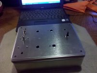
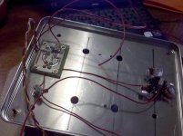
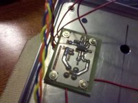
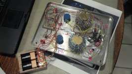
Attached are progress phone photos. I found the same tin at Michael's and added a 1/16th inch aluminum to the inside of the top to stiffen it up a bit. I etched a small board for the opamp section and used the quad opamp in lieu of singles. The resistors are on the bottom of the board. I also included the out bnc in the board. The stepped switches are done, but, not in the photos.
Ken
Attachments
Last edited:
Dick,
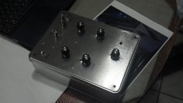
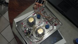
I fired it up this morning and was able to get -60db null without much fiddling. I will work on getting it to -80 this weekend. With the -60db my HP3562A spectrum analyzer showed a noise floor below -120db. Pretty darn good! Photos of the finished box attached. I think I will find a way to cement the trimmers and maybe turn a few of them around so that they can be accessed from the top of the box.
Thanks again for a great design / tool.
Ken
Attachments
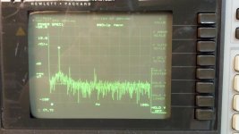
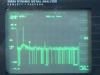
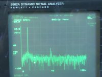
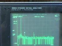
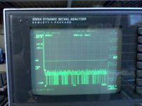
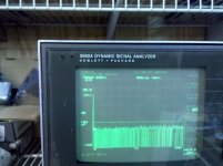
Here are screen shots from my HP3562A spectrum analyzer. The analyzer can resolve 60 to 80 db of signal.
The first photo is with the signal from HP8903A 10kHz 0.5Vrms straight into the analyzer. The signal floor is -90db due to the fundamental being at about -5 db (85 db of resolution). The 2nd, 3rd, etc. harmonics are showing, probably because I'm feeding them directly in the analyzer without a load.
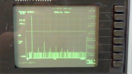
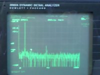
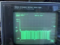
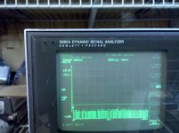
The second photo is the same signal through the Twin -T. You'll see a round circle on the fundamental, it's the marker that displays in the upper left corner - in this instance the null was -77.393db at 10kHz. The horizontal line at approx. -125db (-124.97) was placed by me to represent the noise floor of the analyzer. The second harmonic is at about -103db, the third at about -118db. The spikes at 45kHz are either from the florescent lights or my smart electric meter. I'm pretty confident that this image represents the harmonic profile of the HP8903A signal.
I also tested the slope of the notch by tuning the filter to -80db at 10kHz then feeding it an 11kHz, through 20kHz signal in 1k increments. By 16kHz the notch was not changing the value of the fundamental.
The first photo is with the signal from HP8903A 10kHz 0.5Vrms straight into the analyzer. The signal floor is -90db due to the fundamental being at about -5 db (85 db of resolution). The 2nd, 3rd, etc. harmonics are showing, probably because I'm feeding them directly in the analyzer without a load.
The second photo is the same signal through the Twin -T. You'll see a round circle on the fundamental, it's the marker that displays in the upper left corner - in this instance the null was -77.393db at 10kHz. The horizontal line at approx. -125db (-124.97) was placed by me to represent the noise floor of the analyzer. The second harmonic is at about -103db, the third at about -118db. The spikes at 45kHz are either from the florescent lights or my smart electric meter. I'm pretty confident that this image represents the harmonic profile of the HP8903A signal.
I also tested the slope of the notch by tuning the filter to -80db at 10kHz then feeding it an 11kHz, through 20kHz signal in 1k increments. By 16kHz the notch was not changing the value of the fundamental.
Attachments
Nice work, Ken -- the Twin-T is working great!
Now, about the 8903 -- can you run these tests with a 1kHz fundamental? I'm curious about the oscillator in the 8903. There don't seem to be any THD tweaks for minimizing the 2nd H, and it looks a bit high to me for a 10kHz fundamental. Just curious -- I have an 8903E -- no oscillator -- so I can't check it myself.
Now, about the 8903 -- can you run these tests with a 1kHz fundamental? I'm curious about the oscillator in the 8903. There don't seem to be any THD tweaks for minimizing the 2nd H, and it looks a bit high to me for a 10kHz fundamental. Just curious -- I have an 8903E -- no oscillator -- so I can't check it myself.
Nice work, Ken -- the Twin-T is working great!
Now, about the 8903 -- can you run these tests with a 1kHz fundamental? I'm curious about the oscillator in the 8903. There don't seem to be any THD tweaks for minimizing the 2nd H, and it looks a bit high to me for a 10kHz fundamental. Just curious -- I have an 8903E -- no oscillator -- so I can't check it myself.
Dick,
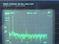
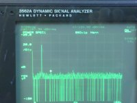
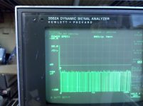
I ran a series of tests, seems the 2nd H varies with the output voltage of the 8903A.
Note that the device is set on auto scale, so, the images jumps around a bit. There is a way to set the upper/lower range, but, I made these images before work today and more importantly, before coffee.
First, I re-ran the 10kHz tests. All voltages are rms. Images as follows:
1. 0.5v 2nd H -103db
2. 0.1v 2nd H -123 (bouncing in the noise floor)
3. 0.2v 2nd H -121
4. 0.3v 2nd H -102
5. 0.4v 2nd H -106
6. 0.6v 2nd H -116
7. 0.7v 2nd H -107
I'll post the 1k results in the next.
Ken
Attachments
-
 IMG_20110928_055955.jpg410.3 KB · Views: 318
 -
 IMG_20110928_060106.jpg417.6 KB · Views: 150
 -
 IMG_20110928_060136.jpg425.7 KB · Views: 141
 -
 IMG_20110928_060227.jpg448 KB · Views: 105
 -
 IMG_20110928_060208.jpg463.6 KB · Views: 109
 -
 IMG_20110928_060153.jpg433.7 KB · Views: 113
 -
 IMG_20110928_060249.jpg479.4 KB · Views: 106
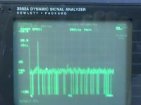
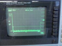
I couldn't get as deep of a null, but, it didn't effect the results. I think that I am going to move the three trimmers to the top of the box for external adjustment as well.
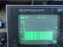
Here are the 1kHz results:
Image:
1. 0.5v 2nd H -100db
2. 0.1v 2nd H -118
3. 0.2v 2nd H -112
4. 0.3v 2nd H -108
5. 0.4v 2nd H -104
6. 0.6v 2nd H -116
7. 0.7v 2nd H -108
8. 1.0v 2nd H -105
I found a Krohn Hite 4402b Oscillator on ebay last week. Hopefully it will arrive before the weekend. I'll post results for it as well.
Ken
Attachments
-
 IMG_20110928_060953-0-5v.jpg495.7 KB · Views: 146
 -
 IMG_20110928_061020-0-1v.jpg528.1 KB · Views: 137
 -
 IMG_20110928_061051-0-2v.jpg520.1 KB · Views: 128
 -
 IMG_20110928_061107-0-3.jpg538.3 KB · Views: 104
 -
 IMG_20110928_061123-0-4.jpg533.7 KB · Views: 97
 -
 IMG_20110928_061135-0-6.jpg543.3 KB · Views: 96
 -
 IMG_20110928_061158-1-0.jpg535 KB · Views: 106
Is this technique/equipment a close relation to Cordell's distortion magnifier?
Andrew, good question, I'm not sure but I think it is close. Dick is more qualified to answer. I think I can explain what this technique does. The specturm analyzer has a resolution of 80 db or so. When you null the fundamental frequency, you are reducing the db range of the signal by the null value. So, with the fundamental at -60 instead of 0 db the analyzer can now theoretcally resolve down to -140 db. The noise floor of the analyzer kicks in at -125. This is all done with the gain setting of the twin t at 0 db. When switched to +20 db the twin t amplifies the fundamental and the harmonics up out of the noise floor of the analyzer, in effect magnifying the distortion.
My tests were with the twin t set at 0db. Mostly because the 2nd H was already above the noise floor. I'll give it a try at +20 and see if the 3rd H is visible.
Ken
- Status
- This old topic is closed. If you want to reopen this topic, contact a moderator using the "Report Post" button.
- Home
- Design & Build
- Equipment & Tools
- Build -- Active Twin-T notch filter for distortion analysis