Hello Klewis,
Do you use symetric or asymetric inputs of the Juli@ ?
FRex.
Hi Frex,
I used the balanced inputs of the Juli@. The setup was HP8903A output (unbalanced), to Pete Millett's sound card adapter > balanced output from adapter > balanced input of the Juli@.
Some of the frequency roll off might be from the sound card adapater asymetric to balanced line drivers. The THAT corp data sheet only rates them to 20kHz.
Ken
Active Twin-T input levels
Hi folks -- just a quick update on the issue of signal levels into the Twin-T. I've needed a better sound card than the one that is built into my PC, which is bandwidth limited by its maximum 96kHz sampling and by its somewhat higher than good noise floor at -120dB referred to near full-scale input.
I have recently acquired an E-MU 0204 USB "sound card" and find its ADC to be a very good device -- 1V, 1kHz THD is well below 0.005% and the noise floor is around -130dB -- much beter than the on-board sound chip in my system. I'll have more accurate data soon. In any case, when used with the Active Twin-T, good harmonic product measurements can be made on fundamentals of 10kHz or more to well below -130dB using the 20dB post-filter gain of the Twin-T.
I'm still in the early stages of evaluation, but I can definitely say that limiting the input to the Twin-T to something around 1VRMS gives the best overall results. At 3V the amps in the Twin-T seem to be sticking their noses into the results. I hope to be able to say something more definitive about this soon and will post here and on my website.
I have also found some rather strange things with a borrowed Juli@ card in terms of audio bandwidth -- it appears that there is some kind of input filtering going on so that using a higher sampling frequency doesn't result in wider measurement bandwidth. In this regard, the EMU 0204 is clearly superior and gives better results if you want to see distortion products out beyond the 22kHz area. The EMU gives good response to about 90kHz with 192kHz sampling, consistent with Nyquist limit filtering.
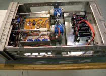
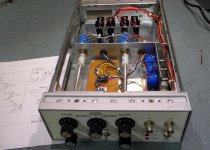
Update on the Active Twin-T and input levels -- four 9V batteries for power keep things clean with inputs up to 8VRMS or so, and with the nominal 1VRMS I usually use, the Active Twin-T appears not to add any measurable distortion. With my build of Bob Cordell's state-variable oscillator IG-18 #2, the BIG-18, configured for moderate output buffer gain, I'm resolving THDs of under 0.00004% at 1kHz, and can't prove that any of that comes from the Twin-T -- but can't disprove it either....
My Implementation of Dick Moore's Active Twin-T
I have been trying to outfit my bench with useful test equipment on a budget. My latest quest is distortion measurement. After a lot of research I have decided to go with a PC based system and Dick's Active Twin-T Notch Filter.
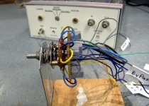
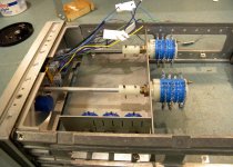
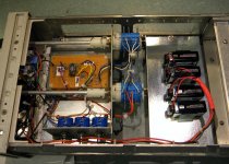
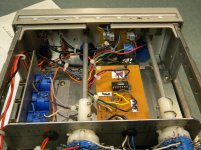
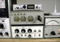
This was a fun project. For the box I re-purposed an HP/Agilent 37203A HP-IB Extender. I found this HP device at a salvage store for cheap and is a common box used by HP to house many of their test equipments including my HP239 Low Distortion Oscillator. This box is a perfect match because I intend to the Twin-T filter with this HP oscillator. The box should also provide excellent shielding.
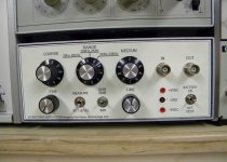
Because of the small front face plate I had to move the 23 position switches further back into the box using DIY extender rods.
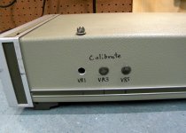
I made no changes to Dick's circuit design. I did add test points to the front to allow me to verify battery voltage without opening the box. I am still looking for front panel knobs that are better suited for this application. But in the interim, these work.
The filter works great and I highly recommend it to anyone on the decision fence. Here are the pictures of my build:
.
I have been trying to outfit my bench with useful test equipment on a budget. My latest quest is distortion measurement. After a lot of research I have decided to go with a PC based system and Dick's Active Twin-T Notch Filter.
This was a fun project. For the box I re-purposed an HP/Agilent 37203A HP-IB Extender. I found this HP device at a salvage store for cheap and is a common box used by HP to house many of their test equipments including my HP239 Low Distortion Oscillator. This box is a perfect match because I intend to the Twin-T filter with this HP oscillator. The box should also provide excellent shielding.
Because of the small front face plate I had to move the 23 position switches further back into the box using DIY extender rods.
I made no changes to Dick's circuit design. I did add test points to the front to allow me to verify battery voltage without opening the box. I am still looking for front panel knobs that are better suited for this application. But in the interim, these work.
The filter works great and I highly recommend it to anyone on the decision fence. Here are the pictures of my build:
.
Attachments
-
 DSCN0483.jpg582.8 KB · Views: 433
 -
 DSCN0487.jpg878.6 KB · Views: 396
 -
 DSCN0554.jpg876.5 KB · Views: 388
 -
 DSCN0555.jpg987.6 KB · Views: 364
 -
 DSCN0556.jpg1,004.9 KB · Views: 369
 -
 DSCN0557.jpg949.4 KB · Views: 229
 -
 DSCN0566.jpg729.3 KB · Views: 209
 -
 DSCN0560.jpg712.7 KB · Views: 222
 -
 DSCN0563.jpg857.1 KB · Views: 239
My Implementation of Dick Moore's Active Twin-T
How does it work? I am still testing and getting acquainted with the Twin-T filter and my new PC based analyzer as a system. My first impression is very promising and I am very excited with my results.
Here are some measurements using my HP239 Oscillator as a source.
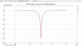
The first screen shot is a response curve of the notch at 1KHz using ARTA/STEPS and my E-MU204 sound card.
Note: I was able to achieve an amazingly low -90dB notch (as measured on other equipment). The STEPS software is not capable of showing the true depth of the notch, however, I feel confident in the accuracy of the notch from 0 to -10dB. You can see very little attenuation at 2Khz where the first harmonic exist. H2 attenuation would only be about -.01dB.
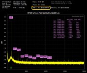
The next screen shot is using my new QuantAsylum QA400 USB Audio Analyzer, HP239 Oscillator and my Twin-T filter. The QA400 reports 0.0125% THD and taking into account the Twin-T -40dB notch, the actual THD of the oscillator is 0.000125%.
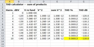
In the final screen shot I further verified the accuracy by calculating the sum of the first 9 harmonics at 0.00013%.
This is a learning process for me. If any of my analysis is incorrect, please set me straight.
Thanks for looking. I also want to thank Dick for all the personal help he provided me, and for sharing his work with everyone. His web site at moorepage.net is an excellent resource for this project as well as his many other useful projects.
.
How does it work? I am still testing and getting acquainted with the Twin-T filter and my new PC based analyzer as a system. My first impression is very promising and I am very excited with my results.
Here are some measurements using my HP239 Oscillator as a source.
The first screen shot is a response curve of the notch at 1KHz using ARTA/STEPS and my E-MU204 sound card.
Note: I was able to achieve an amazingly low -90dB notch (as measured on other equipment). The STEPS software is not capable of showing the true depth of the notch, however, I feel confident in the accuracy of the notch from 0 to -10dB. You can see very little attenuation at 2Khz where the first harmonic exist. H2 attenuation would only be about -.01dB.
The next screen shot is using my new QuantAsylum QA400 USB Audio Analyzer, HP239 Oscillator and my Twin-T filter. The QA400 reports 0.0125% THD and taking into account the Twin-T -40dB notch, the actual THD of the oscillator is 0.000125%.
In the final screen shot I further verified the accuracy by calculating the sum of the first 9 harmonics at 0.00013%.
This is a learning process for me. If any of my analysis is incorrect, please set me straight.
Thanks for looking. I also want to thank Dick for all the personal help he provided me, and for sharing his work with everyone. His web site at moorepage.net is an excellent resource for this project as well as his many other useful projects.
.
Attachments
Last edited:
How does it work? I am still testing and getting acquainted with the Twin-T filter and my new PC based analyzer as a system. My first impression is very promising and I am very excited with my results.
Here are some measurements using my HP239 Oscillator as a source.
The first screen shot is a response curve of the notch at 1KHz using ARTA/STEPS and my E-MU204 sound card.
Note: I was able to achieve an amazingly low -90dB notch (as measured on other equipment). The STEPS software is not capable of showing the true depth of the notch, however, I feel confident in the accuracy of the notch from 0 to -10dB. You can see very little attenuation at 2Khz where the first harmonic exist. H2 attenuation would only be about -.01dB.
The next screen shot is using my new QuantAsylum QA400 USB Audio Analyzer, HP239 Oscillator and my Twin-T filter. The QA400 reports 0.0125% THD and taking into account the Twin-T -40dB notch, the actual THD of the oscillator is 0.000125%.
In the final screen shot I further verified the accuracy by calculating the sum of the first 9 harmonics at 0.00013%.
This is a learning process for me. If any of my analysis is incorrect, please set me straight.
Thanks for looking. I also want to thank Dick for all the personal help he provided me, and for sharing his work with everyone. His web site at moorepage.net is an excellent resource for this project as well as his many other useful projects.
.
Nice job Dennis.
I wish I had access to such junk stores as you but I live in the great white north.
Davada -- I was up there for awhile (B.C.) in May.... beautiful..on a trek to Alaska... but I am glad to be back where it is warmer most of the time.-RNMarsh
If you traveled Alaska Hyw you might have gone through Fort St John.
Just bouncing off the coast all the way up to Alaska... by boat. My Apache lady friend with me... had driven that route a long time ago and it wasnt a good experience. Very hard on vehicles. She is hard core outdoors person and it was still hard. Pretty... but WAY too cold. -RNM
Last edited:
Update on the Active Twin-T and input levels -- four 9V batteries for power keep things clean with inputs up to 8VRMS or so, and with the nominal 1VRMS I usually use, the Active Twin-T appears not to add any measurable distortion. With my build of Bob Cordell's state-variable oscillator IG-18 #2, the BIG-18, configured for moderate output buffer gain, I'm resolving THDs of under 0.00004% at 1kHz, and can't prove that any of that comes from the Twin-T -- but can't disprove it either....
Did you try to use Arta with a deep FFt buffer 132000. This will decrease the noise level in the bins and with the EMU card it gives huge headroom. No need for a twin T filter anymore in normal measurements.
See file with spectrum of tektronix 505 oscillator
Attachments
@JPV -- I have done exactly that and found that using the Active Twin-T made a significant difference. While the 132k buffer definitely lowers the noise, it does not significantly diminish the distortion in the EMU caused by the high level fundamental -- in my case, 1VRMS. I suggest you build a simple passive Twin-T filter for 1kHz that attenuates the fundamental at least 30dB, then check your distortion products again -- remember to add 9.5dB to the 2nd H level and 5dB to the third.
@JPV -- I have done exactly that and found that using the Active Twin-T made a significant difference. While the 132k buffer definitely lowers the noise, it does not significantly diminish the distortion in the EMU caused by the high level fundamental -- in my case, 1VRMS. I suggest you build a simple passive Twin-T filter for 1kHz that attenuates the fundamental at least 30dB, then check your distortion products again -- remember to add 9.5dB to the 2nd H level and 5dB to the third.
I fully agree with you that decreasing the level of the fundamental will decrease the distortion in the EMU. This is the basic definition of non linear distortion: level dependent. My remark is that for normal measurements, the level of distortion is way above the combined distortion of the emu card + very low distortion oscillator at 24 bits but can be buried in noise. Using ARTA with a low distortion oscillator and a deep FFT allows you to measure amazingly low harmonics without having to tune an add on device for each measurement.
There is an interesting test to do IMHO.
At low levels of distortion, it can be shown that :
Let H2 be the ratio of the second harmonic to the fundamental ( fundamental as seen in the spectrum of the output of the DUT and not in the spectrum of the input to the DUT) , H3 the same for the third harmonic. It is well known that H2 is proportional to the square of the test sinusoid and H3 is proportional to the cube.
Let IM2 be the ratio of the second intermodulation product of two sinusoids of same amplitude at frequencies f1 and f2, f2>f1 to the fundamental f1. The second harmonic due to intermodulation will be at f2-f1 and f2+f1, the third IM3 will be at 2f1-f2 and 2f1+f2.
It can be shown that at low frequencies and low distortion levels, the following holds: IM2 = 2 times H2 and IM3=3 H3.
So, by injecting two sinusoids at same level and close frequencies we can look at the intermodulation harmonics that are generated by the EMU. these harmonics are only related to the distortion mechanism in the emu.
But also, the second IM2 will be 6db higher than the second harmonics H2 generated only by the EMU The IM3 will be 9.54 db higher than H3.
From the reading of H2 in the spectrum ( wich contains the harmonic of the oscillator and the harmonic of the EMU) we substract (IM2- 6db) and we have the pristine second harmonic of the oscillator !!!
The same for third harmonic but with 9.54db.
Of course this implies that the harmonics are amplitude adding and there is a phase problem but I think the have the same phase
I would like to do it but I have only one oscillator.
JPV
It is well known that H2 is proportional to the square of the test sinusoid and H3 is proportional to the cube.
This applies only if anything in the signal chain is "weakly nonlinear only", i.e. we're dealing with smooth nonlinearities. This does not hold at all for an ADC or DAC--there are switching devices and other nonlinearities involved which are very difficult to model (in fact, nearly impossible at the current state of the art) and which don't follow such simple rules.
In fact this simple model doesn't even hold for a standard opamp--the class B output stage is not weakly nonlinear anymore, as the transistors switch fully off at some point.
Samuel
Update on the Active Twin-T and input levels -- four 9V batteries for power keep things clean with inputs up to 8VRMS or so, and with the nominal 1VRMS I usually use, the Active Twin-T appears not to add any measurable distortion. With my build of Bob Cordell's state-variable oscillator IG-18 #2, the BIG-18, configured for moderate output buffer gain, I'm resolving THDs of under 0.00004% at 1kHz, and can't prove that any of that comes from the Twin-T -- but can't disprove it either....
Hi, Dick M.,
Q: is there a pcb coming for the active portion of your twin-T? By/from you or other?
Thx - Dick M.
News Flash -- How about using the notch filter in an oscillator with its regenerative feedback disconnected? Built-in multi-freq notch. just add an input port and disconnect switch for the regen circuit.... any oscillator lying around could be a candidate. Wha chu tink?
Thx-RNMarsh
Thx-RNMarsh
Last edited:
- Status
- This old topic is closed. If you want to reopen this topic, contact a moderator using the "Report Post" button.
- Home
- Design & Build
- Equipment & Tools
- Build -- Active Twin-T notch filter for distortion analysis