The past few days I have been working on a variable high voltage power supply, to make life easier.
I decided to create a CCS that outputs a constant current into a reference resistor, with a buffer (gate follower).
View attachment HV laboratory supply.pdf
(I am lost how to get a decent postable picture from my simple drawing tool McCad)
This works like a dream. Very stable. At 2 mV setting of the scope, the output remains completely flat (and our mains is very very fluctuating).
Noise (excluding hum) is almost absent. Less than 0,5 mV.
Hum is visible. Measured on scope less than 3 mV peak-peak 50 Hz, from the pick-up on the long (30 cm) leads to the potmeter I use, and the unshielded 20 turns potentiometer itself.
With a more careful layout and proximity it can be beter even, but hey, 100 dB is not bad. For instance hum already dropped from 10 mV PP to 3 mV PP by earthing the case on the front panel.
The unit ranges from 68 Volt to 315 Volt. This is of course determined by the reference resistor, I choose 100K.
I also added a 6,3 output as that is handy too.
As an extra I think of adding an electronic choke, that also limits the output to about 200 mA.
Albert
An update:
The schema, updated:

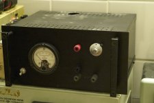
Here is a picture of the outside

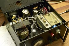
and the somewhat messy insides:

you can see the big rectifier tube 5RU4 and the 6J5 single triode.
I have a big PIO and a starter capacitor (top left) below the provisional voltahe divider for the tube heater. The outside and specs only matter 🙄
The CCS is composed of a 2SK30, that manages the triode's current into 100k.
The active choke was taken from A.M.Quinn's website. I have not yet attached this active choke.
albert
The schema, updated:

Here is a picture of the outside

and the somewhat messy insides:

you can see the big rectifier tube 5RU4 and the 6J5 single triode.
I have a big PIO and a starter capacitor (top left) below the provisional voltahe divider for the tube heater. The outside and specs only matter 🙄
The CCS is composed of a 2SK30, that manages the triode's current into 100k.
The active choke was taken from A.M.Quinn's website. I have not yet attached this active choke.
albert
Love that analog amp meter, inspired me to make my own HV power supply, gonna go tube (6L6 or 6550) with solid state rectifiers.
Simple HV supply, Version 2
Because I saw some hum and other residue when making distortion measurements on my new line amp, I had to improve the supply.
I added a 1.200 uF capacitor after the 10H choke. This completely takes away all line residue. Less than 5 mV peak peak. [And what is left is a bit of hum and some noise from my fluorescent lamps). This raw supply shows a 10 mV flutter from line perturbations (often telematics).
Then I added a RC filter after the voltage reference of 12 K // 4 uF. This filters any noise that gets past the triode or that is generated in this stage. In fact, the reference output shows some low frequency shot noise, short intermittent, spurious peaks of about 1 mV as well as some 50 Herz (from the triode heater I think).
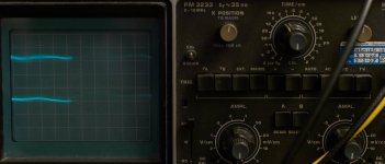
What is left is totally flat. 0,6 mV RMS and less than 1 mV pp on the scope. The thick part of the line that you see is the lighting.
A Salas shunt supply is slightly better, but alas, that is fixed and this is variable: the core capability of a lab supply.

Upper trace: output (2 mV/cm), lower trace, raw supply (5 mV/cm).
Of course a silicon bridge can be used; I just had a 300V AC transformer with 5V winding available plus I have several 5U4 rectifier tubes. These tubes do give a low rectifier hum, and what remains can be filtered. My experience is that solid state bridges are hard to filter.
Because I saw some hum and other residue when making distortion measurements on my new line amp, I had to improve the supply.
I added a 1.200 uF capacitor after the 10H choke. This completely takes away all line residue. Less than 5 mV peak peak. [And what is left is a bit of hum and some noise from my fluorescent lamps). This raw supply shows a 10 mV flutter from line perturbations (often telematics).
Then I added a RC filter after the voltage reference of 12 K // 4 uF. This filters any noise that gets past the triode or that is generated in this stage. In fact, the reference output shows some low frequency shot noise, short intermittent, spurious peaks of about 1 mV as well as some 50 Herz (from the triode heater I think).
What is left is totally flat. 0,6 mV RMS and less than 1 mV pp on the scope. The thick part of the line that you see is the lighting.
A Salas shunt supply is slightly better, but alas, that is fixed and this is variable: the core capability of a lab supply.

Upper trace: output (2 mV/cm), lower trace, raw supply (5 mV/cm).
Of course a silicon bridge can be used; I just had a 300V AC transformer with 5V winding available plus I have several 5U4 rectifier tubes. These tubes do give a low rectifier hum, and what remains can be filtered. My experience is that solid state bridges are hard to filter.
Attachments
- Status
- Not open for further replies.