Hi all
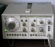
Just wondered whether anyone had come across or played with a LEADER LFG-1300S 0-2Mhz function generator before, or perhaps repaired one ?
I have a 1300S, reliable as you like and a pleasure to use, but switched it on the other day and there was absoloutely no output whatsoever above 100Hz......
Having said that, there is some 'intermittent' output below 100Hz, but it does not tally with the scale readings and is way out-of-range.
It powers up OK, the O/P fuse is fine and all the power supply voltages are spot-on.
A 'stab in the dark' I know, but I have read lots of posts relating to the use and maintenance of Signal Generators here
Cheers, Richard
Thanks very much the tips, audiohead & Enzo ")
The contacts on the range / function switches are all OK, but I have cleaned them with Servisol, just to make absolutely sure.
There are 3 x LM741 op-amps which make up the 'master oscillator' - these were removed and tested (all OK) - but I've replaced them with new ones anyway.
The only other IC I can pin-point as being a likely candidate, is a NE521 comparator, which is now oblesete and no longer manufactured..
Cheers, Richard
Hello Art,
Yes I do - not a brilliant copy, but readable and available here :
LEADER LFG-1300S Service Manual
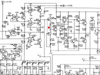
The troubleshooting / faultfinding guide starts on page 14, with the block diagram on page 22 and master generator schematic on page 23.
Perhaps you might just be able to spot something obvious, I've overlooked...
Very many thanks, Richard
Yes I do - not a brilliant copy, but readable and available here :
LEADER LFG-1300S Service Manual
The troubleshooting / faultfinding guide starts on page 14, with the block diagram on page 22 and master generator schematic on page 23.
Perhaps you might just be able to spot something obvious, I've overlooked...
Very many thanks, Richard
I have a high-quality scan of an original LFG-1300S manual. The hard-copy manual cost me almost $35 so I am not releasing it to the multitudes--however send me a PM with your email address and I will send it to you.
The main pages were scanned at 300 dpi in 8-bit gray scale, schematics and block diagrams at 600 dpi.
The main pages were scanned at 300 dpi in 8-bit gray scale, schematics and block diagrams at 600 dpi.
There are 3 x LM741 op-amps which make up the 'master oscillator' - these were removed and tested (all OK) - but I've replaced them with new ones anyway.
More likely a capacitor has failed than a broken lm741. Check for open, shorts or leaks. If the LM741 are in sockets maybe thing about an upgrade, you can improve performance by an order of magnitude for like $2
The good news is that (1) a quality USB audio interface and some software can make a pretty decent audio function generator if the computer audio can run at 96K and (2) if that is not good enough, high end HP gear sells on eBay for <$100. My old generator used to make little spikes on a spectrum display. My "new to me" 40 year old HP generator shows a thin line right on the fundamental and not much else.
Hello everyone - good news...
I'm pleased to say that I have finally managed to repair the function generator
It turned out to be a leaky dual-fet (a IMF3898 ), actually partially short-circuit S-D, the upper of the 2 FET's in the circuit diagram, reading around 3200 ohms.
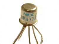
Although an IMF3898 is shown in the parts list for Q105 - a upa71A was originally fitted.
I initially replaced it with a couple of 2N3819's - the generator sprang to life, but would only operate up to approx 800 kHz max.
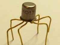
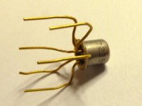
After routing through my spares, I found what looks like a mil-spec device, a WD179 device manufactured in 1972 - date code 7235. I can find no information on it whatsoever, but it tests as a dual N-channel FET using an ATLAS DCA55 semiconductor analyser.
The generator works fine with it fitted up to 2Mhz, albiet at a very high temperature - ouch....
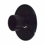
I need a TO18 heatsink if anyone has one - I just can't seem to get one here in the UK and Digikey want £12.50 for shipping one from the USA, which I simply can't justify, for something that weighs no more than 10grams !!
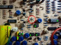
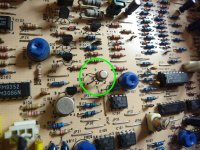
Below are a few photos : I replaced 4 IC's in total : 3 x 741's & a NE521 (SN75107AN equivilent), not that any of them needed replacing - the 4 timing caps were fine, these and the IC's are marked with green dots in the photos. The dual-fet (the culprit) is outlined in red.
Many thanks for everyone's help in getting this fixed - much apreciated guys
Richard
I'm pleased to say that I have finally managed to repair the function generator
It turned out to be a leaky dual-fet (a IMF3898 ), actually partially short-circuit S-D, the upper of the 2 FET's in the circuit diagram, reading around 3200 ohms.
Although an IMF3898 is shown in the parts list for Q105 - a upa71A was originally fitted.
I initially replaced it with a couple of 2N3819's - the generator sprang to life, but would only operate up to approx 800 kHz max.
After routing through my spares, I found what looks like a mil-spec device, a WD179 device manufactured in 1972 - date code 7235. I can find no information on it whatsoever, but it tests as a dual N-channel FET using an ATLAS DCA55 semiconductor analyser.
The generator works fine with it fitted up to 2Mhz, albiet at a very high temperature - ouch....
I need a TO18 heatsink if anyone has one - I just can't seem to get one here in the UK and Digikey want £12.50 for shipping one from the USA, which I simply can't justify, for something that weighs no more than 10grams !!
Below are a few photos : I replaced 4 IC's in total : 3 x 741's & a NE521 (SN75107AN equivilent), not that any of them needed replacing - the 4 timing caps were fine, these and the IC's are marked with green dots in the photos. The dual-fet (the culprit) is outlined in red.
Many thanks for everyone's help in getting this fixed - much apreciated guys
Richard
Attachments
..
I need a TO18 heatsink if anyone has one - I just can't seem to get one here in the UK and Digikey want £12.50 for shipping one from the USA, which I simply can't justify, for something that weighs no more than 10grams !!
I have a circuit running on a breadboard right now, been running now for 72 hours. I improvised a small heat sink with a strip of aluminum cut from a soda can and held in by an alligator clip. Seems to be working well. It cools a part that used to almost burn my finger to one that is just barely warm. The trick is getting good contact.
I have also seen a brass washer used. If the transisor is in a metal can you can make a washer fit by filing out the central hole or adapt a section of copper tube.
Many thanks for the offer Art, that's really very kind of you
I've just had a look at the Toshiba data sheet for the 2SK389. Not sure if this would work reliably up to 2Mhz been designed as an audio device, but I may be wrong - the IMF3958 / upa71A components however, are classed as an RF differential dual-fets. My other concern, although 'not the end of the world' so to speak, is the pin spacing / layout which could be quite fiddly and involve adding sleeved extensions to the closely spaced legs - what do you think ?
Richard
There are a number of listings on eBay for the 2N3958, a direct replacement; also here's a UK source in Surrey.
The dual package was selected for temperature tracking/stability reasons, using separate devices is not recommended.
The dual package was selected for temperature tracking/stability reasons, using separate devices is not recommended.
Leader Lfg 1300s schematics
Hello to you all. I'm looking for some time, for didactic reasons (working in a technical institute) the wiring diagrams of the function generator Leader LFG 1300s. I have seen those kindly provided by timetec, but would appear to partially incorrect: the capacitor C103 has both terminals on the ground, and has continually the Ic106 pin 3 shorted to ground by switch S101.
In particular, I'm looking at the circuit on the low-frequency (hz 0,1-1-10).
The diagram shown in pic 8 seems to be overhauled.
Can you help?
Thanks in advance and greetings to you all.
updating an old thread, I know.
I just bought one of these on ebay and it seems brand new or nearly new. the bnc fiber caps were still all (no one who *uses* the gear leaves bnc caps on, lol).
I wonder if I should upgrade things inside, just for good measure, seeing that its an old-stock item? caps? op-amps?
very pleased with the usability of this FG. nice large dial, marked up to 2.0 for obvious audio use, intelligent layout of controls. very well thought out user interface, which is what drew me to buy this one.
I can't stand to leave 741's inside, though surely I'd get better perf with something more modern? lower noise and cleaner waveforms, perhaps, as a result?
I just bought one of these on ebay and it seems brand new or nearly new. the bnc fiber caps were still all (no one who *uses* the gear leaves bnc caps on, lol).
I wonder if I should upgrade things inside, just for good measure, seeing that its an old-stock item? caps? op-amps?
very pleased with the usability of this FG. nice large dial, marked up to 2.0 for obvious audio use, intelligent layout of controls. very well thought out user interface, which is what drew me to buy this one.
I can't stand to leave 741's inside, though
surely I'd get better perf with something more modern? lower noise and cleaner waveforms, perhaps, as a result?Attachments
This is a good starting point for me too and
I've learned just by viewing.
Having the same types of problems with mine
and also want to upgrade mine after I fix it so
that is why the new thread.
http://www.diyaudio.com/forums/equi...g-1300s-doa-fix-then-upgrade.html#post4216625
I've learned just by viewing.
Having the same types of problems with mine
and also want to upgrade mine after I fix it so
that is why the new thread.
http://www.diyaudio.com/forums/equi...g-1300s-doa-fix-then-upgrade.html#post4216625
Last edited:
I need a TO18 heatsink if anyone has one - I just can't seem to get one here in the UK
Richard
Improvise by using a flat aluminum sheet, give it the shape by using a drill bit, and format it to clamp shape by adding an screw and nut.
A bit of thermal paste (CPU coolers) will offer even more perfection.
- Status
- This old topic is closed. If you want to reopen this topic, contact a moderator using the "Report Post" button.
- Home
- Design & Build
- Equipment & Tools
- LEADER LFG-1300S Function Generator - DEAD