Hi everyone,
Finally managed to complete a simple curve tracer based on Alan Douglas' design. I've made some minor tweaks to use the same setup to measure gm as well. Results have been fantastic so far:
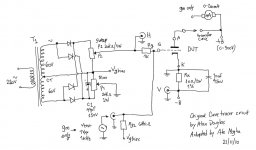
The circuit help us plotting a transfer curve of a triode (Ia versus Vg) which is very helpful in selecting a pair of matches output valves for example. In order to avoid using step generators, this simple circuit relies on a XY oscilloscope. Mine is a OWON digital, which is not very flexible in XY mode (i.e. cannot invert the signal), but does the job for most of what I need.
If you want to measure transconductance (gm) you need a signal generator to produce the delta VG required. Due to my limited sensibility of the OWON, I have to use a 1Vpp in the grid to measure small anode current changes for particular valves.
A variable high voltage supply is better, otherwise you could end up blowing supplies, fuses, etc. as I did")
I have measured many valves 6SN7GT, 6SL7GT, 807, EL34s, etc and have compared with original gm measures from the valve tester and results are pretty close. You can also derive gm from the transfer curve, but you have to rely on your oscilloscope's grid measurement capabilities.
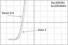
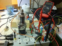
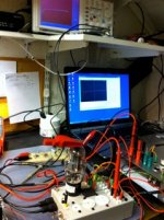
Attached is the circuit diagram, a couple of pictures of my setup and an analysis of 4 different EL34 wired in triode mode which showed a matched trio and the remaining one a bit different
Any suggestions for improvements?
Hope you find this interesting
Cheers,
Ale
Finally managed to complete a simple curve tracer based on Alan Douglas' design. I've made some minor tweaks to use the same setup to measure gm as well. Results have been fantastic so far:
The circuit help us plotting a transfer curve of a triode (Ia versus Vg) which is very helpful in selecting a pair of matches output valves for example. In order to avoid using step generators, this simple circuit relies on a XY oscilloscope. Mine is a OWON digital, which is not very flexible in XY mode (i.e. cannot invert the signal), but does the job for most of what I need.
If you want to measure transconductance (gm) you need a signal generator to produce the delta VG required. Due to my limited sensibility of the OWON, I have to use a 1Vpp in the grid to measure small anode current changes for particular valves.
A variable high voltage supply is better, otherwise you could end up blowing supplies, fuses, etc. as I did
I have measured many valves 6SN7GT, 6SL7GT, 807, EL34s, etc and have compared with original gm measures from the valve tester and results are pretty close. You can also derive gm from the transfer curve, but you have to rely on your oscilloscope's grid measurement capabilities.
Attached is the circuit diagram, a couple of pictures of my setup and an analysis of 4 different EL34 wired in triode mode which showed a matched trio and the remaining one a bit different
Any suggestions for improvements?
Hope you find this interesting
Cheers,
Ale
Attachments
It's gratifying to see that another person has been bitten by the curve tracer bug!
I'm not sure if this is very important to you or not, but if you want to be able to invert the display axes at will, and also want to be able to display any of the three currents versus any of the three voltages (or even just some of them), you could do all of that with simple opamp amplifier circuits. You might need a current-sensing resistance in series with each DUT pin of interest. You might also want to have selectable load resistances (or impedances). The switching and routing might drive you nuts, at first, if you want to be able to display either voltage or current for every pin. But even that's not really too difficult. (If you don't use opamps a lot, look at AN-20 and AN-31 at national.com, and remember to use bypass capacitors on every power pin.)
I'm not sure if this is very important to you or not, but if you want to be able to invert the display axes at will, and also want to be able to display any of the three currents versus any of the three voltages (or even just some of them), you could do all of that with simple opamp amplifier circuits. You might need a current-sensing resistance in series with each DUT pin of interest. You might also want to have selectable load resistances (or impedances). The switching and routing might drive you nuts, at first, if you want to be able to display either voltage or current for every pin. But even that's not really too difficult. (If you don't use opamps a lot, look at AN-20 and AN-31 at national.com, and remember to use bypass capacitors on every power pin.)
It's gratifying to see that another person has been bitten by the curve tracer bug!
I'm not sure if this is very important to you or not, but if you want to be able to invert the display axes at will, and also want to be able to display any of the three currents versus any of the three voltages (or even just some of them), you could do all of that with simple opamp amplifier circuits. You might need a current-sensing resistance in series with each DUT pin of interest. You might also want to have selectable load resistances (or impedances). The switching and routing might drive you nuts, at first, if you want to be able to display either voltage or current for every pin. But even that's not really too difficult. (If you don't use opamps a lot, look at AN-20 and AN-31 at national.com, and remember to use bypass capacitors on every power pin.)
Indeed, I've been bitten by the bug long time ago!
It's very easy to start complicating this and ending up with a ton of routing options and op amps. I've tried to keep the setup as simple and flexible as possible without adding many other parts to the circuit. Having said that, you are right, I could simple add an op amp inverting stage with another amp stage to use when measuring small cathode currents and hence reduce the swing of the control grid voltage to less than 1V (e.g. 0,1V). Also could have added a 1:1 matching transformer to isolate the oscilloscope and being able to measure the anode current instead - but that's an extra cost that I'm not sure if is worth the addition of the transformer.
Any suggested op amp type and circuit for inverting and amplifying the cathode current?
Thanks
Ale
.
Hi, have you been to the audiojumble at Tonbridge in the last few years?
A stallholder there has a very nice homebrew curve tracer that displays the Vg/Ia curve on a 'scope.
Hi there, haven't been there yet. I'm planning to attend next event though
thanks
Ale
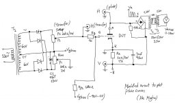
Ale,
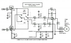
Attached is one way I have done it.
I cheated and used a switch and a unity-gain differential amplifier so I didn't have to use a separate inverting amplifier. But I'm not sure how negative your -B voltage can get. If it's -300 that might be a bit of a problem for this circuit!
Note that you could eliminate C112 and C113 and combine their two 1K resistors into one 2K resistor. And you don't have to use 0.1% resistors, or even 2K/1K values, although the four total resistances should be closely matched. You could also eliminate the three 49.9 Ohm resistors.
When I built this I used OP275 opamps because I had some on hand and they can take up to +/-18V power supply voltages. I think I used +/-17.5V and had inputs ranging between +/-15V. But almost any decent unity-gain-stable opamp that can swing to the voltages you need with your available power supply voltages should work OK.
Cheers,
Tom
Attachments
Last edited:
Ale,
Attached is one way I have done it.
I cheated and used a switch and a unity-gain differential amplifier so I didn't have to use a separate inverting amplifier. But I'm not sure how negative your -B voltage can get. If it's -300 that might be a bit of a problem for this circuit!
Note that you could eliminate C112 and C113 and combine their two 1K resistors into one 2K resistor. And you don't have to use 0.1% resistors, or even 2K/1K values, although the four total resistances should be closely matched. You could also eliminate the three 49.9 Ohm resistors.
When I built this I used OP275 opamps because I had some on hand and they can take up to +/-18V power supply voltages. I think I used +/-17.5V and had inputs ranging between +/-15V. But almost any decent unity-gain-stable opamp that can swing to the voltages you need with your available power supply voltages should work OK.
Cheers,
Tom
Hi Tom,
Thanks for your suggestion, a couple of questions since it has been many years since I last used op amps.
1) the suggested differential amplifier does have unity gain?
2) my supply is 300v (-B to +B) and referenced to gnd is less than 15v due to the cathode current, am I wrong?
3) I do need to filter out the 50hz noise in the vertical signal when I'm measuring low currents, will this circuit help me in rejecting this?
4) with regards to the op amp selection and the power supply, I guess I need to add a voltage regulator circuit to provide suitable supply voltages to the op amps. Eg lm7815/7915 or a simpler circuit. I'm short of space in the valve tracer cabinet, so the simpler the better. Any suggestions?
5) I have to buy the op amp, so any suggestions for this circuit?
Many thanks for your help
Cheers,
Ale
"A mistake is always forgivable, rarely excusable and always unacceptable. " (Robert Fripp)
hi Tom,
Implemented your differential amplifier to invert the vertical signal - just breadboarded it and works fine!
Keen to plot plate curves so was thinking of:
Drive plate with a rectified ac source (0-250v)
Drive gate with a step generator from a DAC and a bit counter - also need to figure out an easy way to amplify the 0-10v to the right gate voltage e.g. -40v to 0v. Perhaps a mosfet amplifier? any suggestions?
Cheers,
Ale
"A mistake is always forgivable, rarely excusable and always unacceptable. " (Robert Fripp)
Implemented your differential amplifier to invert the vertical signal - just breadboarded it and works fine!
Keen to plot plate curves so was thinking of:
Drive plate with a rectified ac source (0-250v)
Drive gate with a step generator from a DAC and a bit counter - also need to figure out an easy way to amplify the 0-10v to the right gate voltage e.g. -40v to 0v. Perhaps a mosfet amplifier? any suggestions?
Cheers,
Ale
An externally hosted image should be here but it was not working when we last tested it.
"A mistake is always forgivable, rarely excusable and always unacceptable. " (Robert Fripp)
hi Tom,
Implemented your differential amplifier to invert the vertical signal - just breadboarded it and works fine!
Keen to plot plate curves so was thinking of:
Drive plate with a rectified ac source (0-250v)
Drive gate with a step generator from a DAC and a bit counter - also need to figure out an easy way to amplify the 0-10v to the right gate voltage e.g. -40v to 0v. Perhaps a mosfet amplifier? any suggestions?
Cheers,
Ale
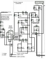
Hi Ale,
Plate curves would be very nice. I'll attach a schematic of the staircase waveform generator I designed. You would have to derive a pulse to drive the Clock input of the counter chip, from your rectified AC plate sweep. My schematic shows some components ahead of the chip's CP (Clock) input, which are there to generate short TTL-level pulses from the leading edges of a longer-duty-cycle 0-8V pulse/square waveform. You might have to tweak that pulse-forming network, to work well with your input. Your input would be one pulse for each AC cycle, so that the staircase waveform would advance to the next stairstep for each AC sweeo of the plate voltage. You could use something like a comparator circuit, to output zero volts whenever your divided-down AC was below some threshold voltage. But maybe even something like a stack of diodes would work, to pick off just the peaks of the AC. Anything that gives one fast-rising edge per cycle should be able to work.
There's probably some other stuff that you might want to change, on that schematic, such as the voltage-offset resistor network above the opamp. And you could probably use non-0.1% resistors and just put a trimmer in each of the four binary-counter-output paths.
To get the 0 to -40V staircase grid voltage, any amplifier that can reach -40V output should work to some degree. You will want an offset-adjust trimmer on it, and probably a fine-tuning trimmer for the gain. If I were doing it, I would probably use a chipamp, such as LM3875, which can have supply voltages up to +/-47V. (Chipamps are easier for me, because they work just like big opamps. So amplifiers are trivial to design with them, and parts count and footprint are low.)
Actually, when I used that staircase generator, I followed it with a step attenuator (and a power amplifier), so I could change the size and total voltage range of the steps. The circuit I attached here puts out 1-Volt steps from 0V to 15V, with +/-17.5V supplies. But you could change any/all of those parameters if you changed the opamp's feeback resistor.
Cheers,
Tom
Attachments
Last edited:
Oops, it looks like the LM3875 chipamp can only have supply voltages up to +/-42 Volts. The LM4780 would be good, too, but has the same supply voltage limits. I think that if you had a fairly high load resistance, compared to the usual audio speaker load, the clipping/dropout voltage spec would go to less than (-Vsupply + 2 Volts), allowing you to get to -40 Volts, but maybe just barely. But there are bound to be many other amplifiers that could do the job.
Hi Tom,
Good suggestions. I will look at the op amp options to see if I can get the 40vpp sweep. I will then add the amplified 40vpp signal to the gate bias supply of my current curve tracer which provides 0 to -100v bias to the gate.
Re the generator tracer, why not dividing the 100hz pulse obtained by conditioning the plate swing rectified voltage as you recommend but then dividing the clock signal by 2 so you can ensure that at least 2 plate swing cycles occur every step change in the gate? Also my oscilloscope has a function to retain 1s or 2s the trace so this could help? By doing I could avoid adding any signal sync as you suggest. Does it make sense?
For the plate swing voltage I was thinking of two 220/12v back to back transformers to produce a 220v 100ma ac signal isolated from the mains. I would then add a variac to the mains to allow a 0-250v plate signal. Have you done anything similar?
Hi there,
Finally used two transformers back to back plus a full wave rectifier to drive the plate. I've made a couple of tests (RCA Royce 45 and a Brimar 807 in tetrode mode) and manually saved each plate curve and combined them afterwards in my computer. Not too tedious, but definitely will build the gate step generator to avoid doing this! Will have to wait for the christmas break to do this
Only point to make is that the 807 curves actually are a combination of the screen and the gate currents since my circuit senses the cathode current only to avoid using a matching transformer in case of sensing the plate current on the anode - which will be way above the 0V ground and will fry my inverting circuit
Cheers,
Ale
Attachments
Last edited:
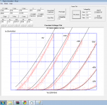
Here I'm again with an interesting application of the valve curve tracer. I used the brilliant SPICE modelling application from James Lanier (K4BPM PSPICE Home Page) and managed to get very closed matching with my Royce 45 by playing with the model parameters. Not easy to do at all, you can follow the instructions from Norman Koren (Improved vacuum tube models for SPICE, Part 1) and I managed to match very closely the -40V and -30V plate curves which are the ones i'm interested in for my SET 45 valve amplifier.
See the attached results. here is the LT Spice model I used with the results above:
.SUBCKT 45 1 2 3 ; P G C; NEW MODEL
+ PARAMS: MU=3.5 EX=1.33 KG1=3615.57 KP=49.50 KVB=4.39 RGI=2000
+ CCG=3.5P CGP=7.5P CCP=3.5P ; ADD .7PF TO ADJACENT PINS; .5 TO OTHERS.
E1 7 0 VALUE=
+{V(1,3)/KP*LOG(1+EXP(KP*(1/MU+V(2,3)/SQRT(KVB+V(1,3)*V(1,3)))))}
RE1 7 0 1G
G1 1 3 VALUE={(PWR(V(7),EX)+PWRS(V(7),EX))/KG1}
RCP 1 3 1G ; TO AVOID FLOATING NODES IN MU-FOLLOWER
C1 2 3 {CCG} ; CATHODE-GRID; WAS 1.6P
C2 2 1 {CGP} ; GRID-PLATE; WAS 1.5P
C3 1 3 {CCP} ; CATHODE-PLATE; WAS 0.5P
D3 5 3 DX ; FOR GRID CURRENT
R1 2 5 {RGI} ; FOR GRID CURRENT
.MODEL DX D(IS=1N RS=1 CJO=10PF TT=1N)
.ENDS
it's great to be able to plot your valve curves and then try to match as closely as posible a SPICE model to support your design work
Will keep working....
Cheers,
Ale
Attachments
- Status
- This old topic is closed. If you want to reopen this topic, contact a moderator using the "Report Post" button.
- Home
- Design & Build
- Equipment & Tools
- Valve curve tracer gm tester