Friend's, Roman's, Countrymen, lend me your ears:
Er,
Richard, Davada, Other's:
So, if I understand y'all correctly I'd do the following:
1. Remove & replace U101 w LT1468 pin 8 bend up.
a. thus c132,c133,c135 have no effect.
davada's recommend to remove compensation from U101:
2. Remove c130, c131, c134? replace with bus wire?
Why wouldn't I also replace U100 while I'm in there?
3. Then the AGC to JFet, trim pot, TP103 w/
the 3K 10-22 turn pot.
4. Bipolars to c111 c112
5. Looking around for the 2H level trim pot...
5K 20 - 28 turn...
Looking for the other bipolar locations
and the other pot to change.
Have to find the other output level too,
but I'll get there as time permits.
Attachments
Last edited:
Friend's, Roman's, Countrymen, lend me your ears:
Er,
Richard, Davada, Other's:
So, if I understand y'all correctly I'd do the following:
1. Remove & replace U101 w LT1468 pin 8 bend up.
a. thus c132,c133,c135 have no effect.
davada's recommend to remove compensation from U101:
2. Remove c130, c131, c134? replace with bus wire?
Why wouldn't I also replace U100 while I'm in there?
3. Then the AGC to JFet, trim pot, TP103 w/
the 3K 10-22 turn pot.
4. Bipolars to c111 c112
5. Looking around for the 2H level trim pot...
5K 20 - 28 turn...
Looking for the other bipolar locations
and the other pot to change.
Have to find the other output level too,
but I'll get there as time permits.
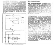
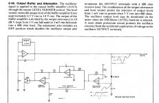
If you're going to replace op amps in the analyzer you will need to adjust the FB cap value.
If you look at the data sheet for the LT1468 or design notes for the same, There is a formula for calculating the FB cap value. However it typically about 7pF to 10pF depending on the value of FB resistor and circuit gain. Remove the 100 ohm decoupling resistor it reduces the current in the FB path. You may need to adjust the FB cap value to flatten the band width.
No reason not to change the buffer amp in the oscillator but RM found the stock to better job.
The is no second H trim pot you have to add that.
Last edited:
I have tried the amp/buffer following the oscillator. It seems like a natural to do also. I have not seen consistent improvement.... but it wont hurt either. I have several 339a here and on the first one I changed every opamp and other IC's. I could get very low distortion but not at all ranges and not over the widest freq range.
The changes recommended from all this is a good compromise. Here is what you can expect from 100Hz - 10KHz -- Slightly more at lower/higher freqs but always below .001% -->
.jpg")
.jpg")
[Click and zoom in]
PS - the 2H trim pot is to replace a fixed resistor between the drain and gate of the jFET. Your schematic does not show such resistor. Mine does.
THx-RNMarsh
The changes recommended from all this is a good compromise. Here is what you can expect from 100Hz - 10KHz -- Slightly more at lower/higher freqs but always below .001% -->
[Click and zoom in]
PS - the 2H trim pot is to replace a fixed resistor between the drain and gate of the jFET. Your schematic does not show such resistor. Mine does.
THx-RNMarsh
Last edited:
I have to wait on this.
I need to acquire a 339A first.
Wondering if anyone might be interested in trading a 339A
for an excellent condition TEK 2246MOD A. I actually think
the scope was never used or lightly used. Everything works
was previously calibrated.
It a 100MHYz four-channel, dual-sweep, "portable" scope.
I need to acquire a 339A first.
Wondering if anyone might be interested in trading a 339A
for an excellent condition TEK 2246MOD A. I actually think
the scope was never used or lightly used. Everything works
was previously calibrated.
It a 100MHYz four-channel, dual-sweep, "portable" scope.
PS - the 2H trim pot is to replace a fixed resistor between the drain and gate of the jFET. Your schematic does not show such resistor. Mine does. THx-RNMarsh
Ok, I assume the placement of the trim pot is at Q100, between
the Drain and after the junction of G1, G2 prior to R114 @ 5K.
First start with a 339A schematic.... bought off the Internet to do most any type of changes.
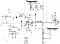
The jFET feedback R51/2K. Replace with 28 turn pot/trimmer. It is in series with a 60mfd cap (C30)..... together they go from jFET gate to its' drain. Replace with 100mfd 105c bipolar.
The Oscillator Amplitude Adjust pot (R30/2K) might replace it as this old has contact issues and makes the adjustment difficult and 'touchy'. Replace.
The output pot is R3 (10K). Replace.
These and the osc IC - U1 (LT1468) is all you need to do to have the level of THD shown above.
If you want to reduce that 2H further, replace the oscillator output buffer (U3... with pin 8 removed) with another LT1468. Then you get this residual level:

[all that 'grass' is 120Hz power supply ripple... guess this one could use some new/larger filter cap replacements]
Now, Harmonics are between -135dB and -145dB.
THx-RNMarsh
The jFET feedback R51/2K. Replace with 28 turn pot/trimmer. It is in series with a 60mfd cap (C30)..... together they go from jFET gate to its' drain. Replace with 100mfd 105c bipolar.
The Oscillator Amplitude Adjust pot (R30/2K) might replace it as this old has contact issues and makes the adjustment difficult and 'touchy'. Replace.
The output pot is R3 (10K). Replace.
These and the osc IC - U1 (LT1468) is all you need to do to have the level of THD shown above.
If you want to reduce that 2H further, replace the oscillator output buffer (U3... with pin 8 removed) with another LT1468. Then you get this residual level:
[all that 'grass' is 120Hz power supply ripple... guess this one could use some new/larger filter cap replacements]
Now, Harmonics are between -135dB and -145dB.
THx-RNMarsh
Last edited:
Ok, I assume the placement of the trim pot is at Q100, between
the Drain and after the junction of G1, G2 prior to R114 @ 5K.
Your looking at the wrong schematic. The trim pot goes in the oscillator. The schematic shown is the input of the analyzer.
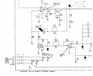
I put the trim on R50 but I guess it doesn't matter which R it replaces.
I feel like such an Aggie.
David, Richard,
Thank you for straightening me out. Yes, I got the schematic from
Agilent online shame on me. I'll have to buy a "new" clean scanned
schematic. I'm waiting for a 339A before moving forward.
But when I get one, at least I won't be changing the wrong parts.
Thanks again.
David, Richard,
Thank you for straightening me out. Yes, I got the schematic from
Agilent online shame on me. I'll have to buy a "new" clean scanned
schematic. I'm waiting for a 339A before moving forward.
But when I get one, at least I won't be changing the wrong parts.
Thanks again.
This what you can expect from a little work.... osc is well below -100dB but noise limits the analyzer to -100dB. Here are two units i did last year --- you can click on them and then zoom in for detailed view. It's a loop-thru test of itself. It's 1 volt monitor output signal could go to an ADC/ FFT unit (such as the QA400):

THx-RNMarsh
THx-RNMarsh
Last edited:
This what you can expect from a little work.... osc is well below -100dB but noise limits the analyzer to -100dB. Here are two units i did last year --- you can click on them and then zoom in for detailed view. It's a loop-thru test of itself. It's 1 volt monitor output signal could go to an ADC/ FFT unit (such as the QA400):
View attachment 414821
THx-RNMarsh
What's the photo in the background?
May I ask what your application is where 339a is useful ?
Cheers
A modern amplifier will have MUCH lower distortion then a 339a is able to measure. You will just get "zero". But the 339 is very us full for development of amplifier stages. For example you have a triode (tube) gain stage and wput azine wave on the computer's audi ant to see what B+ voltage gets best result. You can run an experiment. Same goes for testing audio transformers.
But a modern design amp with NFB is going to measure "0.0 THD".
SO for amplifiers I use software. You output a sine wave on the computer's audio interface and then send the amp's output to a dummy load and the audio interface input. Then run an FFT and plot spectra. If yu have a high quality 24-bit USB audio interface box you can get better results than with the 339. But the 339 is better for bench use when developing ampler stages and parts.
Unfortunately, so far the ADC linearity in sound cards limits their "stand alone" use to the same -100dB. Only (so far) with a notch filter on the fundamental prior to the ADC input, you can go down lower.
THx- RNMarsh
No it does not work that way. No notch filter. The audio from the dummy load is sent directly to the audio interface. The software computes an FFT using thousands of data points. The harmonics are summed. The process is sensitive enough for measure THD in the best amplifiers
You can also calibrate the system by replacing the amplifier with a length of wire to see your zero point.
What's happened is that today a computer based audio spectrum analyzer is nearly free if we happen to already have most of the parts (audio interface, computer, software) and the audio meter is expensive. Back when the 339 was build computers a spectra in real time was very expensive.
Back when the 339 was build computers a spectra in real time was very expensive.
Back in the day, say 1980, was the ability to FFT a primary signal with -100db resolution even possible? I'm asking out of ignorance...
Regardless, the tools afforded us by computer A/D and software is amazing, but the boat anchors still have their place. (setting pots on the DUT with the big beautiful panel meter, and looking at the distortion residual come immediately to mind)
Hello, the 339A is very helpful. If nothing else, they can be used as an input for the sound card, adjusting the sound card's input signal level so that it does not over load or get burned out. The 339A notch filter will also extend the range of the FFT by about 100dB (theoretically).A modern amplifier will have MUCH lower distortion then a 339a is able to measure. You will just get "zero". But the 339 is very us full for development of amplifier stages. For example you have a triode (tube) gain stage and wput azine wave on the computer's audi ant to see what B+ voltage gets best result. You can run an experiment. Same goes for testing audio transformers.
But a modern design amp with NFB is going to measure "0.0 THD".
SO for amplifiers I use software. You output a sine wave on the computer's audio interface and then send the amp's output to a dummy load and the audio interface input. Then run an FFT and plot spectra. If yu have a high quality 24-bit USB audio interface box you can get better results than with the 339. But the 339 is better for bench use when developing ampler stages and parts.
Even if you have a 24-bit, you will not get 24-bit accuracy. The electronics is limited by the OP-AMP used. It will certainly not do 24-bit.
You'll be lucky to get 20-bit if everything is working ideally.
- Home
- Design & Build
- Equipment & Tools
- HP339A distortion analyser