Hello,
Does anyone would be interested by an high-end analog to digital converter ?
For my own use, i develop a new ADC .It's main use is a high performance measurements tool, for testing my DIY audio projects.
It's main features are :
Cirrus Logic CS5381KZZ 24 bits 192kHz flagship ADC
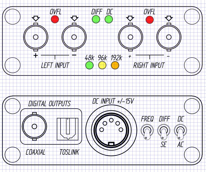
Fully differential and single-ended switchable analog inputs.
AC and DC coupling input switchable.
48, 96 and 192kHz on the fly selectable sampling rate.
Optical (toslink) and BNC SPDIF digital outputs.
Very small from factor (120x70x20mm)
Zero calibration allow all offset cancellation.
+/-10V FS input sensitivity.
Standard SMD or TentLab Master clock oscillator
Need +/-15Vdc power supply (SSR01/02 or other low noise PS. Allow 4 wires with sense connexions)
Use MAX3000 PLD functions controlling (no uC)
Allow low-cost or Scientific-Conversion High-end SPDIF digital transformer.
This is my 2nd ADC design (the first use the AK5394 ADC).
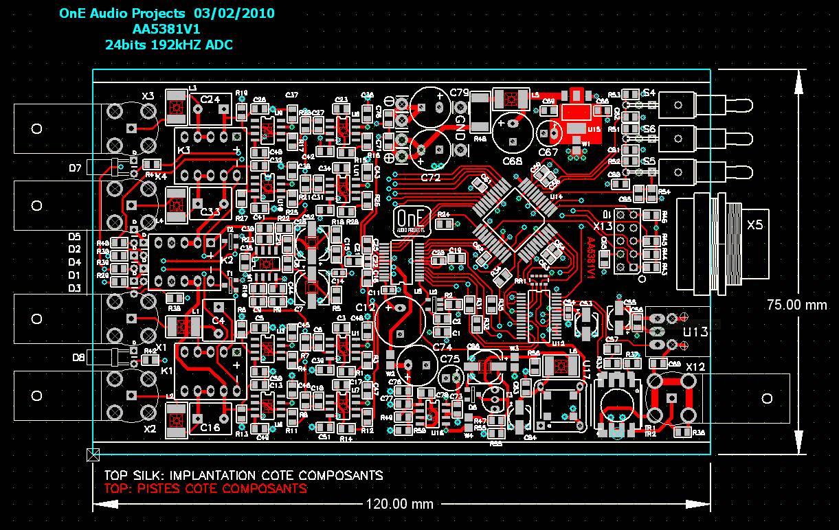
Here the PCB design use 4 layers with massive ground plane and very clean signal path routing
Now, the schematics and the PCB design is done, but not already sent to the PCB manufacturer.
I verify again and again each one before to order it.
If some DIYers are interested by this project, i can post more details about it.
Below, You can see what it should look like.
Frex
Does anyone would be interested by an high-end analog to digital converter ?
For my own use, i develop a new ADC .It's main use is a high performance measurements tool, for testing my DIY audio projects.
It's main features are :
Cirrus Logic CS5381KZZ 24 bits 192kHz flagship ADC
Fully differential and single-ended switchable analog inputs.
AC and DC coupling input switchable.
48, 96 and 192kHz on the fly selectable sampling rate.
Optical (toslink) and BNC SPDIF digital outputs.
Very small from factor (120x70x20mm)
Zero calibration allow all offset cancellation.
+/-10V FS input sensitivity.
Standard SMD or TentLab Master clock oscillator
Need +/-15Vdc power supply (SSR01/02 or other low noise PS. Allow 4 wires with sense connexions)
Use MAX3000 PLD functions controlling (no uC)
Allow low-cost or Scientific-Conversion High-end SPDIF digital transformer.
This is my 2nd ADC design (the first use the AK5394 ADC).
Here the PCB design use 4 layers with massive ground plane and very clean signal path routing
Now, the schematics and the PCB design is done, but not already sent to the PCB manufacturer.
I verify again and again each one before to order it.
If some DIYers are interested by this project, i can post more details about it.
Below, You can see what it should look like.
Frex
Very interested - the only similar project I'm aware of is AD24QS - Audio Analog to Digital Converter 24 Bit / 192 kHz
Audio ADC, the schematic...
Hello,
With only one reply, i'm not really sure that many people are interested by the project. 😎
I post the full schematic in pdf, constructive comments are welcome.
----) AA5381v1Sch.pdf
Below, the PCB design finished (only the top layer is displayed).
The ADC is designed as audio measurements tool. It replace a sound card, with more easy to use because it's an external unit with direct BNC connexion.
It allow DC or AC coupling, single ended or differential input, offset calibration,
overload detection on each channel and 48/92 and 192kHz sampling rate are supported.
The digital output can use optical or coaxial link (SPDIF).
It need only a low noise dual rail +/-15V dc power supply.
I wait comments...
Frex.
Hi Frex
Impressive pcb work, fine.
Maybe you are looking for something readymade, and possible unbeatable, take a look at TI's PCM4222EVM ( US $ 149,-- +shipping ).
You just need a dual 15V and single 5V powersupply.
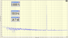
Here a FFT; source Krohn-Hite 4400A, both units SLA battery driven, PC interface RME-PAD via AES/EBU.
Impressive pcb work, fine.
Maybe you are looking for something readymade, and possible unbeatable, take a look at TI's PCM4222EVM ( US $ 149,-- +shipping ).
You just need a dual 15V and single 5V powersupply.
Here a FFT; source Krohn-Hite 4400A, both units SLA battery driven, PC interface RME-PAD via AES/EBU.
Attachments
Last edited:
I have already build another high-end ADC, with AK5394.
It's actually my measurement reference, largely better than I/O of my ESI Juli@ sound card. I know the PCM4222 from TI, it's also a top grade ADC chip.
I prefer largely build my own device, for many reason.
First for the pleasure (DIY or not DIY !).
Second, it's technically very interesting to investigate on each steps
of this type of design.
Third, i build exactly for my need, with all convenience i want.
I love too when the finished work is "beautiful" to look.
About the spectrum of the EVM, how exactly the measure has been done ?
Digital, analog, all setup ?..
Frex
About the spectrum of the EVM, how exactly the measure has been done ?
Digital, analog, all setup ?
Analog oscillator KROHN-HITE 4400A ( SLA battery driven ) -> unbalanced to PCM4222EVM ( SLA Battery driven ) ->
AES/EBU-out to AES/EBU-in RME-Digi96/8-PAD -> Spectralab 5.0 demo.
Gary
Hello, Frex.
I think this is an interesting project. However, I do not understand how it works. Could you explain how to acquire and analyze the converted digital signal? Do you have software that will do real-time analysis of a digital stream?
Thanks for sharing it with us!
I think this is an interesting project. However, I do not understand how it works. Could you explain how to acquire and analyze the converted digital signal? Do you have software that will do real-time analysis of a digital stream?
Thanks for sharing it with us!
Hello,
It's easy to use.
The ADC has a SPDIF digital output, then you need in your PC a sound card
with digital input. Be careful, if you want use the ADC at high sampling rate the SPDIF input of your sound card must support it.
I personally use the ESI "Juli@", it's a low cost solution and very powerful solution (~100$).
After that, you can make all processing you want with the digital stream with appropriate software. Many FFT software are available to do that.
Spectralab is one of the best, but it's very expensive.
Oscillometerz is also very good software.
All of this software allow to make real-time processing including FFT spectrum and much more...
Frex
ADC comments
You're probably a little impatient, give us a few days to chew over your good work😀
Some comments:
1. +-15v supplies are bad for portability. Think +-12 or even +-9V.
2. Put TWO pre-amp options on: one for adjustable for audio levels and one fixed that can see right down to the thermal floor, which means using a low-noise opamp like AD797 or LT1028 in the first stage.
<puts flamesuit on>
Hello,
With only one reply, i'm not really sure that many people are interested by the project. 😎
I post the full schematic in pdf, constructive comments are welcome.
----) AA5381v1Sch.pdf
Below, the PCB design finished (only the top layer is displayed).
The ADC is designed as audio measurements tool. It replace a sound card, with more easy to use because it's an external unit with direct BNC connexion.
It allow DC or AC coupling, single ended or differential input, offset calibration,
overload detection on each channel and 48/92 and 192kHz sampling rate are supported.
The digital output can use optical or coaxial link (SPDIF).
It need only a low noise dual rail +/-15V dc power supply.
I wait comments...
Frex.
Hello noisewarrior,
Your comment is welcome. I'm not so impatient.😀
The ADC has been designed for +/-15v supply, but it can be supply with +/-12V without modification. For +/-9v operation, it need probably only slight modifications.
In my schematic, the analog input stage use OPA134, because i want use this instrument with many sources of signal, with high and low source impedance.
The opa134 is very good compromise for high input impedance, low voltage noise and very good THD specifications.
LT1028 and AD797 are the lowest noise available AOP, but it's bias current is very high and current noise too.
Any "single" AOP can be use in place of the OPA134.
Of course, maybe sligh value modifications can be done for optimisation.
Last thing, if you change OPA134 with LT1028/AD797, you must add much more $$. 😉
Hello everyone,
I think now soon send Gerber files for pcb manufacturing. 🙂
I think use "pcbcart" service. It' offer cost effective solution and they job is very good.(145€ for 2 boards including shipping).
I hope that my job doesn't yet contain many errors.🙄
Frex
I think now soon send Gerber files for pcb manufacturing. 🙂
I think use "pcbcart" service. It' offer cost effective solution and they job is very good.(145€ for 2 boards including shipping).
I hope that my job doesn't yet contain many errors.🙄
Frex
ghg,
Thanks for the good tip, but that -168dB floor in your plot, is relative to what voltage?
Thanks for the good tip, but that -168dB floor in your plot, is relative to what voltage?
Hi Frex
Impressive pcb work, fine.
Maybe you are looking for something readymade, and possible unbeatable, take a look at TI's PCM4222EVM ( US $ 149,-- +shipping ).
You just need a dual 15V and single 5V powersupply.
Here a FFT; source Krohn-Hite 4400A, both units SLA battery driven, PC interface RME-PAD via AES/EBU.
Ghg, I would also like to know the full setup of of your measurements.
A fully detailed explanation will be welcome 🙂
Frex
A fully detailed explanation will be welcome 🙂
Frex
Analog oscillator:
KROHN-HITE 4400A ( SLA battery driven ) unbalanced, 50 Ohm output
ADC:
PCM4222EVM ( SLA Battery driven ) AES/EBU-output
PC interface:
RME-Digi96/8-PAD AES/EBU input
FFT software:
Spectraplus 5.0 demo (download at SpectraPLUS - Audio Spectrum Analyzer)
fs=44.1kHz, 1048576 points, Blackman, 24 bit.
What additional info do you need ?
Gary
ghg,
What is the rms level of the analyzed signal ?
The spectrum analyzer is it calibrated in real dBv ?
It will be interesting to make measurements with higher sampling rate,
because noise increase.
Do you use weighting filter ?
Can you post more pictures ?
Frex
What is the rms level of the analyzed signal ?
The spectrum analyzer is it calibrated in real dBv ?
It will be interesting to make measurements with higher sampling rate,
because noise increase.
Do you use weighting filter ?
Can you post more pictures ?
Frex
I have ordered 2 PCB at pcbcart.
I wait them in about 18 days.
of course, i will post a picture as soon it arrived. 😉
Frex
I wait them in about 18 days.
of course, i will post a picture as soon it arrived. 😉
Frex
One concern I have with using ADC designs for testing is that it is too easy to blow up the front end with too much voltage. What do you think about adding a voltage divider and/or diode clamps before the first opamp stage? The DIY oscilloscope mentioned elsewhere here and detailed at:
DPScope - A Low-Cost PC-Based Oscilloscope
uses both.
DPScope - A Low-Cost PC-Based Oscilloscope
uses both.
Hello grenert,
I essentially test audio devices. In my many tests, with my first ADC design using AKM5394, i have never damaged the input stage.
Of course, if you test an audio amplifier outputs, the voltage can be higher than tens volts, and you need to add a divider to fit to the input scale of the ADC.
But i agree, about the need to protect inputs if the device is intended for high voltage measurements.
If your are interested by the ADC, you can easily add your own attenuator (maybe internal..).
The adding resistors ladder network for the input attenuator and a protection diodes at OPAMP inputs, it degrade noise performance and can cause non-linearity and distortion (leakage current).
Frex.
(For the next version of the pcb design, i will add protection diodes which could be solder only if necessary) 🙂
As i have already wrote, the PCB was sent to manufacturer, and i wait it for the next week. I will post pictures of the PCB as soon i will receive it.
I must be patient now...
Fortunately, i can work on others audio projects pending. 🙂
Frex.
final schematics :AA5381v1sch
I must be patient now...
Fortunately, i can work on others audio projects pending. 🙂
Frex.
final schematics :AA5381v1sch
- Home
- Design & Build
- Equipment & Tools
- DIY Analog-to-Digital Converter project.Audio measurements tool