Hi Folks,
I am normally found around the tube amp forums but have recently brached into the dreaded solid state to build a function generator.
I built this around the 8038 chip as described on this site -
8038 Audio Generator Project
The generator is up and running and does everything that it is supposed to do except that the signal (Sine, square and Triangle) is quite ...fat. On my analogue CRO, the trace is about 4mm thick and looks as if the CRO is out of focus (similar but not quite as bad with my digital scope). The CRO is not the problem as I have borrowed an off-the-shelf frunction generator which displays a very precise and clear line.
I can't imagine that this output would be considered acceptable. I have fiddled with all the trimpots with no improvements. Is there anyone out there with any ideas or potential solutions? I have attached the schematic and built exactly as per the description on the website.
Thanks in advance,
Rob
Attachments
Could it be oscillating? Do you have supply decoupling / bypass caps close to the opamps? Not shown in your schematic.
Also, your link to the project doesn't work for me.
Also, your link to the project doesn't work for me.
Hi John,
Thanks for the reply. The layout of the components is per the printed circuit board on the link. It looks like a pretty well thought out design. I am not sure what is wrong with the link, it works on my computer but I have included the URL without the http: (so you can view the link directly) - maybe this may help
//mypeoplepc.com/members/scottnoanh/birthofasynth/id32.html
I gues it could be oscillating but I to be honest I am not sure how to tell. When I look closely at the trace it looks like it is made up of lots of individual lines. In other words the thickness of the line seems to be a result of lots of sine (square or triangle) waves all slightly out of sync by a few microseconds.
Rob
Check pins 2, 3, and 9 of the 8083, see if you have a clean trace there. If so, then at least that you get a clean function out of the IC. If not clean, then you need to check the operating parameters of the 8083, power supply, etc.
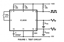
There's a test circuit for the 8083 in the datasheet, see attachment. If I were you I'd breadboard it and power it with two batteries. Then I'd change one thing at a time and continue to measure it, until you make one change that gets that thick trace again.
There's a test circuit for the 8083 in the datasheet, see attachment. If I were you I'd breadboard it and power it with two batteries. Then I'd change one thing at a time and continue to measure it, until you make one change that gets that thick trace again.
Attachments
Has to be oscillating. As said above, check that you have bypass caps near each chip. Also check your wire/trace routing to be sure you haven't created a positive feedback path to an opamp input by daisy chaining grounds. Reminds me of my first sig gen, a SWTP kit from back in the '70s. The main difference was that it used the dreaded LM318 for an output amp- without good bypassing those were absolutely guaranteed to oscillate!
Are there bypass near/on the pins of the output buffer op-amps?
Sorry, DigitalJunkie, I don't think I understand the question. The layout is extactly as per the PCB board on the website.
Hi Ikoflexor,
Good advice with respect to the output of the pins. Makes sense. At least then I can narrow it down to the power supply or rest of the circuit. It's not the IC - I have 2 8038's and have swapped them over without any change. Thanks also for the test cicuit - I will try and get one of those breadboards this afternoon.
Cheers,
Rob
Has to be oscillating. As said above, check that you have bypass caps near each chip. Also check your wire/trace routing to be sure you haven't created a positive feedback path to an opamp input by daisy chaining grounds. Reminds me of my first sig gen, a SWTP kit from back in the '70s. The main difference was that it used the dreaded LM318 for an output amp- without good bypassing those were absolutely guaranteed to oscillate!
Howdy Conrad,
Now I am sitting bolt upright and taking note. I grounded the whole thing with a daisychain loop - a great description. I hesitate to ask the question but - is this bad? It certainly makes for a neat layout.
I would never do this with a valve amp (big copper earth bus always) but I figured that it wouldn't matter with IC's.
If you think this might be a problem, let me know!! More importantly how should it be grounded? Star?
Cheers,
Rob
Always star ground. You may want to power it with batteries to eliminate the psu from the picture, while testing.
OK,
Here is a quick update before my wife kills me if I don't get up to bed.
The 8038 has the dirty trace on the pins so I am presuming my problem may be in the power supply.
The only unusual thing that I can see is that there is a 1KHz ripple on both 'in' pins on the VR IC3 and IC4 (PDF 2) but the ripple is only present on the 'out' pin of IC4. I have changed the elecrolytic cap (C9) associated with IC4 - no change. Also changed C6 - no change.
Is this ripple normal or is it abnormal and if so could it account for the 8038 distortion? Could a leaky C8 cause this?
Thanks again,
Rob
1Khz ripple on the Input pins of the regs? That's def. a bypassing issue.(regulator(s) oscillating),IME. Add a 0.1uf(or thereabouts) cap in parallel with C8 and C9. It might also be a good idea to add a small electrolytic in parallel with C5 and C6,say 10uf.
My previous comment was about bypass caps on the power supply pins of the op-amps.I notice it says that C3 and C4 should be near IC2,so I assume that they are indeed present.
It might also be good to add some very near the power supply pins of IC1 also.
I think the small caps in parallel with C8 and C9 should clear it up though.
First, try bypassing as described above. It's hard to describe what you can get away with in terms of grounding. Sometimes daisy chaining works ok. Other times not.
You can draw your schematic as the board is wired, replacing every trace (just around the amps) with a small resistor symbol. Then look at your positive op-amp inputs and see if signals can generate any voltage across those "new" resistors you've drawn. That's a positive feedback path that can cause oscillations. You probably won't solve anything immediately this way, but it helps with overall understanding of the situation.
It would be really helpful if you could determine if it's the op-amps or 8038 that's oscillating, but often once something gets going, the signal shows up everywhere. Can you run just the 8038 and probe it's outputs?
Can you expand the "fuzz" on the scope and get an idea of the frequency? AC couple and turn the 8038 frequency way down low or disable it entirely.
I don't know if it's on-line or still available, but look for an old Intersil note called "Everything you always wanted to know about the 8038 but were afraid to ask", or something like that. It had a lot of useful hints.
Ah, here- www.intersil.com/data/an/an013.pdf
Best,
Conrad
Last edited:
1Khz ripple on the Input pins of the regs? That's def. a bypassing issue.(regulator(s) oscillating),IME. Add a 0.1uf(or thereabouts) cap in parallel with C8 and C9. It might also be a good idea to add a small electrolytic in parallel with C5 and C6,say 10uf.
My previous comment was about bypass caps on the power supply pins of the op-amps.I notice it says that C3 and C4 should be near IC2,so I assume that they are indeed present.
It might also be good to add some very near the power supply pins of IC1 also.
I think the small caps in parallel with C8 and C9 should clear it up though.
Hi DigitalJunkie,
I will bypass this evening with the 0.1uF caps in parallel with C8 and C9 but hasn't this allready been achieved with the C5 and C6 caps? Obviously not but I don't understand this.
C3 and C4 definitely present. In fact I made the suggested PCB on the website so everything is the same as suggested by the designer.
Hi Conrad,
I have expanded the fuzz out and it is not so much fuzz but a 'ribbon' (or rainbow) of multiple single traces - sine, square or triangle - all slightly out of phase by a couple of microseconds. It seems to go away when I turn the output of the 8038 right down. Also, the grounding is probably not the issue in this case as I have played around with a few different grounding schemes without any change at all - shame, it would have been a simple solution.
Anyhow, it would be easier just to buy a damn function generator but I am determined to solve this and I am sure I will learn a lot in the process.
Cheers,
Rob
If you remove C2, it stops putting out any signal and you can observe the residual disturbances. The problem might be in the -12V stabilizer. Note its pinout is different than that of the +12V.
If you remove C2, it stops putting out any signal and you can observe the residual disturbances. The problem might be in the -12V stabilizer. Note its pinout is different than that of the +12V.
Hi Oshifis,
Thanks for the advice. I am struggling with this. Taking out C2 does seem to improve things. If I replace with a 0.1uf cap or greater the trace is clean and sharp but unfortunately the adjustable frequency is then quite low. Anything less than the 0.1uf and the trace is dirty again. Can you explain to me what you see as the problem with the pinout?
Hi digitaljunkie, bypassed as suggested with no joy. Also bypassed C7 - no improvement.
This is doing my head in😡
Rob
If audio frequencies is all you need, don't bother making a signal generator. Download Audacity and use it with a good sound card. It's a signal generator, oscilloscope, and spectrum analyzer, as long as you only need audio frequencies.
This shouldn't be that hard, which leads me to believe there's some error in the design or construction. Be sure to download and read the 8038 data sheet and the "everything" sheet. You might find the old Southwest Technical Products FG-2 schematic interesting, though it's quite a bit different than this one. They went with split supplies rather than running the chip on the negative side and offsetting the opamps as done with your design. Google will turn all those up quickly.
C2 is the timing cap. You need that, and you need to confirm that it's what it's suppose to be. The official test circuit uses 3300pF, so 4700pF should be fine. It works in conjunction with the voltage on pin 8 to set the frequency. There should be no AC signal on pin 8. If it were me, I'd start by pulling IC2 and setting a voltage on pin 8 per the test circuit, then look at pins 2, 3 and 9 to see what the waveforms look like. If they're good, I'd find out what's wrong with the stuff driving pin 8. I don't like that sweep and manual control circuit much because it's all high impedance. If it picks up anything at all, you'll see it as a modulation of the waveforms. Maybe you don't have oscillation, but are just seeing that. You might try sticking a big cap, 1uF maybe, from pin 2 to pin 3 of IC2a. BTW, I don't think a TL074 is really fast enough to do a good job with the square wave output of an 8038.
Best,
Conrad
The oscillation on the input pins of the reg's seems odd to me unless the grounding is poor and the scope probe's ground was connected to a bad spot,or if the PSU is a bit on the small side.
What's the voltage on the input pins of the regulator? it should be atleast ~+/-15Vdc.
What's the voltage on the input pins of the regulator? it should be atleast ~+/-15Vdc.
And are C8 and C9 mounted very close to the regs? If not, you need small bypasses on the inputs of the regs right at the regs. Agreed, the PS should certainly not have oscillations!
If audio frequencies is all you need, don't bother making a signal generator. Download Audacity and use it with a good sound card. It's a signal generator, oscilloscope, and spectrum analyzer, as long as you only need audio frequencies.
Of course but where would be the fun in that😉
Ok Conrad - you are absolutely correct, it should not be this hard and that is what is driving me nuts.
Now, i have some more info. When i look closely at the trace it gets 'fatter' as it moves from the triggering point on the left of the CRO screen to the right. I think that this represents an output of varying frequencies rather than multiple frequencies out of phase - pin 8.
This in conjunction with the findings so far lead me to think that it is a problem with the input signal on pin 8 - I did after all find an AC ripple on the -12v supply.
The next step I think is to beef up the 4.7uf Cap to see if this kills the ripple and then if this does not work, replace the -12v VR.
Will report back.
Rob
- Status
- Not open for further replies.
- Home
- Design & Build
- Equipment & Tools
- DIY 8038 Function Generator Problem