Hi,
For a long time, I’ve wanted to design and build a 3 axis CNC routing machine to reduce the time building cabinets (with better results). I’ve had a few thoughts and here are some of the problems I envisage…
The 3rd axis (Vertical Z axis): I assume a motorised screw would be sufficient.
Measurement of movement: This has to be accurate but at the same time, should be irrespective of tolerances in the drive to the motor. For instance, counting the number of turns on a motor is not sufficient if the belt has stretched etc.
Cutting Through: If you are cutting all the way through the baffle (for instance) how would you not damage the router’s base?
SOFTWARE: We would need software to interpret the simple, but extensive CNC language. The programmes are 70-80 A4 pages of instructions for relatively simple shapes.
Is there any interest? Is this possible for not too much money? I would like to build it so that it could be scaled to larger or smaller work, as people require. For my application, I would want it to be 1500mm cutting distance in length and 700mm cutting distance in width. The maximum height would be 50mm.
Thanks,
Gaz
The least expensive units I've seen in Canada are about Cdn$1000 per square foot work area, so the unit you would want would be around $20K. That said, you could probably still build your own for about $6K-8K. Still no small feat.
Unfortunately, you would probably have to spend around $1500 for the CAM software (which usually comes free with the commercial units). Your choices will depend on your current CAD software. Your website shows you are using some kind of 3D modeler, so compatibility with that is your first priority when choosing CAM.
You'll need to decide whether you want to go with stepper motors or servo motors. Steppers are slower but cheaper. Servos are faster and usually don't have any position errors but are more expensive due to the more complex controllers (position feedback) required.
Other than the controller, I'm guessing that the single most expensive components will be the linear bearings and the ball-screws needed for such a big work table.
I'll bet you've already decided on whether you want your machine to be 2-1/2 axis or a full 3-axis. For most panel work, 3-axis units are probably not needed, but it could make for some interesting 3D surfaces.
One thing about cutting through work pieces. It is always good policy to have a throwaway layer mounted to the machine work table. That way, any mistakes usually won't drill their way into the machine but only the throwaway layer. It's also good practice to add the extra layer, then machine it's surface down flat using the router. That way, your Z-axis is always referenced to a consistent altitude.
Sounds like fun. Good luck. I'll check back when I return to work as I have a number of links there from some research I did when our department bought a small unit.
") ensen.
ensen.
Unfortunately, you would probably have to spend around $1500 for the CAM software (which usually comes free with the commercial units). Your choices will depend on your current CAD software. Your website shows you are using some kind of 3D modeler, so compatibility with that is your first priority when choosing CAM.
You'll need to decide whether you want to go with stepper motors or servo motors. Steppers are slower but cheaper. Servos are faster and usually don't have any position errors but are more expensive due to the more complex controllers (position feedback) required.
Other than the controller, I'm guessing that the single most expensive components will be the linear bearings and the ball-screws needed for such a big work table.
I'll bet you've already decided on whether you want your machine to be 2-1/2 axis or a full 3-axis. For most panel work, 3-axis units are probably not needed, but it could make for some interesting 3D surfaces.
One thing about cutting through work pieces. It is always good policy to have a throwaway layer mounted to the machine work table. That way, any mistakes usually won't drill their way into the machine but only the throwaway layer. It's also good practice to add the extra layer, then machine it's surface down flat using the router. That way, your Z-axis is always referenced to a consistent altitude.
Sounds like fun. Good luck. I'll check back when I return to work as I have a number of links there from some research I did when our department bought a small unit.
ensen.Hi,
Thanks for the reply. At the moment, I use 3D Studio MAX and then export to AutoCAD 2002...There must be plugins available, if not I could write one...Maybe!
I have assumed I would use Stepper motors with a severly down geared drive to get good resolution. I do not know much about Servo motors. I do not believe that this project would cost anything like that amount...I'm sure it could be done for under £1000 (about $1500)
I do not intend for the router to be able to change it's "angle of attack" on the work piece. Just XY movements and up and down. Is this 2-1/2 movement?
I suppose I'm not looking for amazing accuracy, just better than I could do with a line and a jigsaw!
That's a great idea for a throwaway layer...as always, I was making things more complicated than they really needed to be.
I have had another idea for the software. About 3 years ago I made a custom protocol and programme that would create instructions for a router using a black and white image, this was for a PCB CNC machine I was planning on building. I could convert this to do the same job, cutting out a huge cost. I could also make it quite specific to speaker building.
Thanks,
Gaz
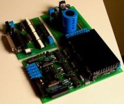
www.nc-step.de Just built the electronics for an uncle. He bought it there with all the steppers and metalwork. It is offered as a kit without casing for the electronics.
This is what you get concerning electronics. The boards are CNCed of course. Looks very good and I am curious about the results of the machine. Bearings and steppers are very high industrial quality material. The steppers are Vexta C8872-9212K or Teco L2108. Everthing was shipped with datasheets and a good manual. Maybe I can make some PCB's with it
Attachments
Thanks for all this info. I have decided on the following:
Static bed. All movement is handled on the "bridge" that moves up and down the long bed. I think this is more suited to tall thin speaker panels that I make.
Attempt to build this for a standard router. Routers have four screws underneath their bases. It's be nice to interface any router to this and enable the user to calibrate the machine per session (or routing bit).
I am still not sure how to fix the wood to the bed without interupting the edges. For instance, the obvious choice would be to have runners the butt up to the sides and tighten it in from each of the four sides. Lets suppose for a second that we want to route the edges whether it be with a bevel or mitre routing bit. The router would hit these runners. Any ideas?!
Stepper motors sound like they could be good enough, as long as they move the router fast enough so as not to burn the wood...Anyone? Assuming an accuracy of +-0.1mm it'd be sensible to have 1 rotation to 0.1mm. I can't imagine this being too difficult (?!)
Thanks,
Gaz
Rarkov said:Hi,
Thanks for the reply. At the moment, I use 3D Studio MAX and then export to AutoCAD 2002...There must be plugins available, if not I could write one...Maybe!
AutoCAD will export to DXF, which is a plain text, ASCII file. Not sure of the precise contents of a DXF file, but a Google search will turn up something. As I understand it, though, a DXF contains the point data to create lines, curves, and text. You could probably create the NC path in AutoCAD, then export it to DXF. Your custom controller software could read the DXF, and translate it into instructions to send to the controller. Simple in theory, but much harder in execution, especially if you want to optimize the NC path.
Jean-Paul's link shows promise, although I'm not certain if it comes with software. Their english site doesn't appear to say, and the documentation PDF (on the English download page) is in German.
Good luck,
Mark Broker
Rarkov said:I am still not sure how to fix the wood to the bed without interupting the edges. For instance, the obvious choice would be to have runners the butt up to the sides and tighten it in from each of the four sides. Lets suppose for a second that we want to route the edges whether it be with a bevel or mitre routing bit. The router would hit these runners. Any ideas?!
Your best bet would be a vacuum table. If you build a chamber below the bed and then have a set up program that uses a 1mm drill bit to run holes every 10mm or so, then all you need to do is connect a high power domestic or industrial vacuum to the plenium chamber to suck the air out. This is how some industrial cnc machines work.
If you were machining parts smaller than the bed, you could just use some disposeable bits of thin hardboard, or even a binbag would work, to blank of the unused areas.
As I have more woodworking tools than I can shake a stick at, I don't have any personal need for one of these, (or room!) but if someone could design a PCB milling version that ran on a mac with a USB interface, I would definately be up for one
pinkmouse said:
Your best bet would be a vacuum table. If you build a chamber below the bed and then have a set up program that uses a 1mm drill bit to run holes every 10mm or so, then all you need to do is connect a high power domestic or industrial vacuum to the plenium chamber to suck the air out. This is how some industrial cnc machines work.
....
 sounds like a reverse air-hockey table. if you can find an old air-hockey game on ebay or something, you're probably halfway there...
faustian bargin said:
Good thinking, "out of the box", as those management consultants like to say!
But don't they mostly have perforated metal as the pitch?
i don't know the answer to that one. i haven't played air hockey in a long time...i would guess some are wood (mdf or masonite) and some are metal.
...
'out of the box' is not difficult when you've never actually been 'in the box' to begin with. i'm an architect, not a speaker builder, nor machinist, nor electrical engineer...wacky ideas (most of them unfeasible) are about all i have.
...
'out of the box' is not difficult when you've never actually been 'in the box' to begin with. i'm an architect, not a speaker builder, nor machinist, nor electrical engineer...wacky ideas (most of them unfeasible) are about all i have.
Hee hee, I'm an architect in SF also, and your philosophy is the same way I justify my presence here on DIY. Sometimes we get lucky with the wacky ideas.I think most air hockey tables are made from MDF with a melamine coating. It can be bought with this layer on it. I'd be more interested in making an air hockey table with the cnc machine than vice versa. I considered making my own table when I discovered the Melamine MDF, but then calculated the number of (hand drilled?)holes...............
I'm up for this project If you decide to go ahead.
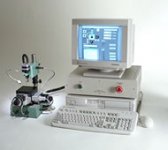
I just bought one of these CNC mini mills for PC boards etc.
Anyone else have one or know where I can get more info on using it? It's my first CNC and I'm not 100% sure on how to start.
I'm dreaming of being able to make double sided PCB's with .9999 fine silver traces.
http://www.minitoolinc.com/microdrillingandpunching.htm
Attachments
2 more cents
Apparently, the slowing US dollar means my Canadian 2 cents is worth more today than when I last posted...
2-1/2 axis means that the Z-axis only goes up or down, but does not provide variable altitude. Full 3-axis can also position the Z-axis at specified points.
Anyway...for ideas try some of the actual manufacturers:
http://www.camtech.ca/home.htm
http://www.cheapcnc.com
http://www.deskproto.com/links/cncmachines.htm
Note that deskproto is a CAM software mfg company.
There are others. I checked my files and my google search terms were "cheap cnc".
I don't know what is in Europe, but Oriental Motor makes well-known and excellent steppers. Also check out a technique called micro-stepping which can increase your travel speeds and your accuracy for a bit of added control complexity.
If you can get an old pen plotter like an HP 7475 or something similar, then you can rip out the controller boards and use it direct out of a CAD program. Of course, you'd have to calculate your own tool paths, but that is a really fast and cheap way to get a controller. Also, you might have to scale it up at the cost of some accuracy, but if you are not doing particularly complicated cuts, then it might be just right.
ensen
Apparently, the slowing US dollar means my Canadian 2 cents is worth more today than when I last posted...
2-1/2 axis means that the Z-axis only goes up or down, but does not provide variable altitude. Full 3-axis can also position the Z-axis at specified points.
Anyway...for ideas try some of the actual manufacturers:
http://www.camtech.ca/home.htm
http://www.cheapcnc.com
http://www.deskproto.com/links/cncmachines.htm
Note that deskproto is a CAM software mfg company.
There are others. I checked my files and my google search terms were "cheap cnc".
I don't know what is in Europe, but Oriental Motor makes well-known and excellent steppers. Also check out a technique called micro-stepping which can increase your travel speeds and your accuracy for a bit of added control complexity.
If you can get an old pen plotter like an HP 7475 or something similar, then you can rip out the controller boards and use it direct out of a CAD program. Of course, you'd have to calculate your own tool paths, but that is a really fast and cheap way to get a controller. Also, you might have to scale it up at the cost of some accuracy, but if you are not doing particularly complicated cuts, then it might be just right.
ensenWe built a similar machine using parts bought on eBay for under $400 including the 3 channel stepper driver which is driven from the parallel port of a Pentium 166.
Search on eBay for:
Steppers: "NEMA 23", "NEMA 34"
6-12volts, 1.8 deg/step or smaller.
Six or eight wire motors are required, unipolar motors won't work with the driver board we used.
Driver: "Stepper Driver" "Stepper 3"
The Stepper 3 is what we used. $99.00
"Lead screw", "Ball screw"
"Linear bearing", "Linear rail"
I don't remember the software used but it's DOS based and understands G-Code.
Email me if more info needed,
Emory
Me, again.
Speaker cabinets, I presume?
You might want to look at NEMA 56 motors
instead of the 23s and 34s I mentioned.
They will handle the heavy plywood, particle board and MDF you'll likely be using. Our machine was built for small routing and engraving jobs. We use NEMA 23s.
E
Speaker cabinets, I presume?
You might want to look at NEMA 56 motors
instead of the 23s and 34s I mentioned.
They will handle the heavy plywood, particle board and MDF you'll likely be using. Our machine was built for small routing and engraving jobs. We use NEMA 23s.
E
- Status
- This old topic is closed. If you want to reopen this topic, contact a moderator using the "Report Post" button.
- Home
- Design & Build
- Equipment & Tools
- DIYAudio CNC Router