L3-3 cards for non russian tubes
Thanks for the link, but as you can see, it is no more available. Would you (or anybody else) like to help us by providing another way to download those files?
Regards from Bucharest,
Cezar, YO3FHM
Hello Oleg,Hi guys! 162 cards for non russian tubes in sPlan format is here _http://slil.ru/28906942. Free viewer is here _http://www.abacom-online.de/uk/html/splan.html
Thanks for the link, but as you can see, it is no more available. Would you (or anybody else) like to help us by providing another way to download those files?
Regards from Bucharest,
Cezar, YO3FHM
I have one of these, but I've not had the time to start using it. I did try the link above but no luck. Does anyone have cards for non-russian tubes ?
Also my 'push to test' switch has gone to heaven, does anyone know where spares can be obtained ?
Thanks in advance")
Here are some links that you may be able to use to work it the other way around. Look for the tube number you have and see if there is a Russian equivalent and use the Russian tube card. You may have already tried this, but here it is if you have not.
Frank's Electron tube Pages
http://www.worldtubecompany.com/mm5/merchant.mvc?Screen=TSL-RUSSIAN
Tubes datasheets
Home Page
As for the push to test button, what part failed? The button or the contacts?
L3-3 schematic diagram and steps to debug the 250V stab.
Hello all L3-3 users,
Somebody put in my hands an L3-3 made in 1986, in good condition, kept as replacement for another "production" one that has been in an old mil base.
I am a beginner in tube matters. This is my first contact with a tube tester, and I never dreamed to one as L3-3, because of it's price. Well, I've started to work on it a couple of days ago, Fri 01.10.2010. After 12 hours of running at half of the mains (110V), I've put it on nominal mains - 220Vac and tried to apply the preliminary checks describved by Seraph and after that, to run the calibration steps and checks described in the translations of Greg (Klemkosky).
Many of them passed, but a few failed:
- at the checking of 250V voltage, I cannot adjust R169 to obtain more than 133V;
- on the calibration of microampermeter, pushing the button "N3MEPEHNE" and adjusting R125 located to the right of the switch, the pointer cannot reach the calibration mark (120);
- while trying to calibrate the tester for measuring the slope (S): after toggling the "S" switch to " калибр" position and holding the measuring button " ИЗМЕРЕНИЕ", the pointer cannot reach the calibration mark (as in the previous step described above).
Well, while I have the service manual (but I don't have the operating instructions manual !!!), I've located in the schematic diagram the 250V stabilizer and started to debug it. I've found C34 (originally as 0.047uF/400V) with a 10x value (0.5uF) and with losses (2.2Mohm) !
I've replaced it with 2 x 0.022uF/400V and the stab started to work normally. Much more than that, now I am able to calibrate the tester for slope measurment and for the low currents.
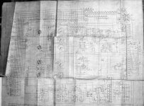
I am attaching here the following documents (following the links, you will jump on an subfolder located on my server, where you can also download the documents, as a mirror to this diyAudio location):
- the entire schematic diagram of the L3-3 tube tester ;
- photo of the 250Vcc stabilizer board, without it's tubes (L16,L17);
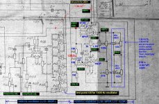
- the schematic of the 250Vcc stabilizer, commented with the static voltages on every hot point, test-points and component values;
- photo of the old C34 located on the rear of 250Vcc stab board;
- photo of the new C34 located on the rear of 250Vcc stab board;
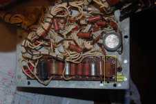
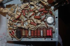
- photo of the power board, where you can find the 250V stab electrolytic capacitors and the EQ resistors;
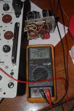
- photo of the 250Vcc voltage check with a digital multimeter;
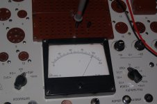
- photo of the 250Vcc voltage check with the L3-3 own meter.
I hope that these informations will help another L3-3 users, if they will encounter the same problems.
Best of luck,
Cezar, YO3FHM
Hello all L3-3 users,
Somebody put in my hands an L3-3 made in 1986, in good condition, kept as replacement for another "production" one that has been in an old mil base.
I am a beginner in tube matters. This is my first contact with a tube tester, and I never dreamed to one as L3-3, because of it's price. Well, I've started to work on it a couple of days ago, Fri 01.10.2010. After 12 hours of running at half of the mains (110V), I've put it on nominal mains - 220Vac and tried to apply the preliminary checks describved by Seraph and after that, to run the calibration steps and checks described in the translations of Greg (Klemkosky).
Many of them passed, but a few failed:
- at the checking of 250V voltage, I cannot adjust R169 to obtain more than 133V;
- on the calibration of microampermeter, pushing the button "N3MEPEHNE" and adjusting R125 located to the right of the switch, the pointer cannot reach the calibration mark (120);
- while trying to calibrate the tester for measuring the slope (S): after toggling the "S" switch to " калибр" position and holding the measuring button " ИЗМЕРЕНИЕ", the pointer cannot reach the calibration mark (as in the previous step described above).
Well, while I have the service manual (but I don't have the operating instructions manual !!!), I've located in the schematic diagram the 250V stabilizer and started to debug it. I've found C34 (originally as 0.047uF/400V) with a 10x value (0.5uF) and with losses (2.2Mohm) !
I've replaced it with 2 x 0.022uF/400V and the stab started to work normally. Much more than that, now I am able to calibrate the tester for slope measurment and for the low currents.
I am attaching here the following documents (following the links, you will jump on an subfolder located on my server, where you can also download the documents, as a mirror to this diyAudio location):
- the entire schematic diagram of the L3-3 tube tester ;
- photo of the 250Vcc stabilizer board, without it's tubes (L16,L17);
- the schematic of the 250Vcc stabilizer, commented with the static voltages on every hot point, test-points and component values;
- photo of the old C34 located on the rear of 250Vcc stab board;
- photo of the new C34 located on the rear of 250Vcc stab board;
- photo of the power board, where you can find the 250V stab electrolytic capacitors and the EQ resistors;
- photo of the 250Vcc voltage check with a digital multimeter;
- photo of the 250Vcc voltage check with the L3-3 own meter.
I hope that these informations will help another L3-3 users, if they will encounter the same problems.
Best of luck,
Cezar, YO3FHM
Attachments
-
 L3-3_schematic.jpg485.6 KB · Views: 659
 -
 stab250V+osc1400Hz-B.jpg198.9 KB · Views: 663
 -
 C34old.JPG510.8 KB · Views: 677
 -
 250V_Stab_board.JPG581.9 KB · Views: 345
 -
 pwr_board.JPG531.6 KB · Views: 624
 -
 C34new.JPG506.3 KB · Views: 647
 -
 250V_check2.JPG905.8 KB · Views: 309
 -
 250V_check1.JPG335.5 KB · Views: 350
L3-3 250V stabilizer schematic ERRATA
I'm coming back to mention a small error on my commented schematic diagram of the 250V stabilizer of L3-3 tube tester: the test point for the internal 1400Hz signal generator is 4/I (and not 4/II). I've corrected this in the picture stored on my website, but not also in the previous post, because simply I have no way to do it. For the record, I am attaching here the corrected schematic.
Sorry for the error!
Best regards,
Cezar
Attachments
GU50 transconductance ?
Hello all,
I tried to measure (using my L3-3 tube tester) the Ia and Ig2 of a GU50 tube, but I didn't encountered any movement of the meter when I tried to measure the "S" .
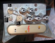
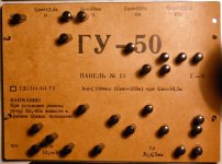
I am attaching the picture of my GU50 test card, because I didn't understood well if I have to adjust the voltage on the first grid (Uc1) or if it must be fixed, as it is programmed by the card ...
... so, if somebody could enlight me with these, I will be grateful !
P.S.> for those who understand Russian, here are the words written in the left side of the GU50 test card:
"ВНИМАНИЕ!
При установке режима ручку Uc1-65в вывестии в крайнее правое положение."
I tried to translate it via Google translator; using also my own interpretation, I believe that the above text should mean " "WARNING! For the manual establishment of the regime, you need to adjust the Uc1-65v from the right side of the panel".
Is this correct?
Thanks a lot,
Cezar
Hello all,
I tried to measure (using my L3-3 tube tester) the Ia and Ig2 of a GU50 tube, but I didn't encountered any movement of the meter when I tried to measure the "S" .
I am attaching the picture of my GU50 test card, because I didn't understood well if I have to adjust the voltage on the first grid (Uc1) or if it must be fixed, as it is programmed by the card ...
... so, if somebody could enlight me with these, I will be grateful !
P.S.> for those who understand Russian, here are the words written in the left side of the GU50 test card:
"ВНИМАНИЕ!
При установке режима ручку Uc1-65в вывестии в крайнее правое положение."
I tried to translate it via Google translator; using also my own interpretation, I believe that the above text should mean " "WARNING! For the manual establishment of the regime, you need to adjust the Uc1-65v from the right side of the panel".
Is this correct?
Thanks a lot,
Cezar
Attachments
Hello Linuksguru,You seem to use wrong card. This card is used to measure
a) leakage current between cathode and filament
b) (reverse) current of second grid
There should be another card to measure transconductance "S".
Thank you for the answer!
It's my first contact with a tube tester and I have to understand some "tips & tricks". I understood what you said above, but is obviously that I couldn't reach this information without external help, hi.
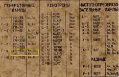
After I've read your explanation, I've downloaded the PDF file cotaining all of the L3-3 test-cards posted on the Jogis-Roehrenbude.de site. At the page 5/205, the GU50 tube is listed, but with one single card only, designed to measure only the parameters that you've mentioned above. I am attaching the snapshot of that page from the document, with a yellow area that marks the GU50 position.
So, while {
1) there is no other test-card for GU50 to measure slope ;
and
2) I am a beginner in such matters };
... well, do you think that you could help me to set another test-card for
GU50, in a way in which I may test it's transconductance ?
This information could be very useful also for others, that may encounter similar problems using different types of tubes. I know that is linked to the understanding of the areas of the test-card, but I repeat, a good helping hand from another experienced people, will be very appreciated !
Thank you very much,
Cezar
Attachments
Hi, LinuxGuru! Thanks for the notice.Looks like there are no perforated card to measure transconductance of GU50, you have to construct it by yourself, but I'm in doubt its possible without external adapter with higher plate voltage (800 - 1000 V).
As I said, I'm a beginner in tube matters; about the mutual conductance, I learned that is the ratio between the change in the anode current and the corresponding change in the grid voltage (written as gm = dIa/dUg1), while the tube has a constant anode voltage (Ua = const.).
It is obviously that I don't know how my L3-3 is measuring the transconductance; otherwise, I should be capable to conclude the same thing as you, or to figure out some trick.
Well, I saw that in the GU50 documentation, the mutual conductance is given in a specific conditions: Ua = 800V, Ug2 = 250V, Ia = 50mA and g1 voltage increment = 5V. I think that you said "higher plate voltage" especially because you probably saw the specs of the tube.
However, I think that gm should be measured also using a different set of polarisation voltages for the tube elements. Probably, in this situation, the final result will be different, but there must be one !
My problem is that I need to be teached about how to set the test-card in a way in which a tube (no matter is GU50 now!) could be checked for the slope (gm), although the anodic voltage is under the limits specified by the datasheet.
Thanks a lot,
Cezar
I think its possible to measure transconductance "S" of GU50 with plate voltage (Ua) supplied by L3-3 - 450V (or whatever). It will be somewhat different from "standard" in data sheet measured at Ua = 800V, but still meaningful. But you have to make this perforated card by yourself. It should not be very difficult.
WARNING about EF89 Arthur Rudolph test card
Hello all,
Looking on the german Russisches Röhrenprüfgerät L3-3 site for informations about my L3-3 tube tester, I found in the links at the end of the first page, an URL that points to the Mr. Arthur Rudolph L1-3 test-cards, made with SPlan for the european tube types.
I was very happy to find a way to design my own test-cards and much more than that, to use a lot of those already made by A.Rudolph. So, I installed the SPlan (there is also an SPLan viewer link) and printed out the EF89 test card.
While on the same site, but at the L1-3 section, the author said:
The result: after 1 minute, I noticed some weak smoke going out from the inside of my L3-3 Of course, I shutted down it immediately, and opened its top panel to see what happened there. Lucky me, there was only a wired resistor overheated, but nothing critical.
After this unpleasant event, I've studied much more the schematic diagram of the L1-3 and also L3-3 tube testers... and I've found that the EF89 test card generated by Mr. A. Rudolph is wrong at least on the following pins:
test deck I:
Until then, I would like to ask any enthusiast to help me (and us) in this matter, to prevent further damages of our test units. Also, I will try to contact Mr. A.Rudolph about this problem.
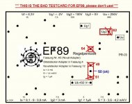
I am attaching here the snapshot of the bad EF89 test-card, for study purpouse only (don't try to use it!).
Best regards,
Cezar
Hello all,
Looking on the german Russisches Röhrenprüfgerät L3-3 site for informations about my L3-3 tube tester, I found in the links at the end of the first page, an URL that points to the Mr. Arthur Rudolph L1-3 test-cards, made with SPlan for the european tube types.
I was very happy to find a way to design my own test-cards and much more than that, to use a lot of those already made by A.Rudolph. So, I installed the SPlan (there is also an SPLan viewer link) and printed out the EF89 test card.
While on the same site, but at the L1-3 section, the author said:
...well, i put the EF89 test card in my L3-3 and started to plant the pins in their designated holes.The L1-3 corresponds to the L3-3 , on this side over here Tube Tester. Das L1-3 ist der Vorläufer, der einzige Unterschied ist techn. The L1-3 is the precursor, the only difference is technical.
The result: after 1 minute, I noticed some weak smoke going out from the inside of my L3-3
Of course, I shutted down it immediately, and opened its top panel to see what happened there. Lucky me, there was only a wired resistor overheated, but nothing critical. After this unpleasant event, I've studied much more the schematic diagram of the L1-3 and also L3-3 tube testers... and I've found that the EF89 test card generated by Mr. A. Rudolph is wrong at least on the following pins:
test deck I:
- 63 (Ug2) must not be there;
- pins 49,50,51; instead, only the 50/I must be set! 49 and 51 must be removed, because their role is to set the cathode pin of the tested tube.
Until then, I would like to ask any enthusiast to help me (and us) in this matter, to prevent further damages of our test units. Also, I will try to contact Mr. A.Rudolph about this problem.
I am attaching here the snapshot of the bad EF89 test-card, for study purpouse only (don't try to use it!).
Best regards,
Cezar
Attachments
The original L3-3 operating manual in Russian (HTML version)
Hello all,
I've found the TECHNOANTIQUE russian site, where the L3-3 original operating manual (in Russian) is hosted in HTML form. The advantage is that portions of the text could be copied and then pasted into Google translator, with a very good rate of translation.
This is the link:
http://technoantique.narod.ru/lab/L3/L_3/instruction.htm
I will return to post a new question about a problem that I've encountered while trying to calibrate the Wien bridge for slope measurment, and there you will see that I've used portions of the russian manual translated with Google directly from the site quoted above.
WARNING! In the first part of the russian document, there are some wrong links. Clicking on them, will port you to an error message default web page. The trick to correctly point to the appropriate page is to correct the backslashes ( \ ) that appears in that links. Hi.
Example:
http://technoantique.narod.ru/lab/L3/L_3/appendixes\appendix3.jpg (wrong)
the correct form is:
http://technoantique.narod.ru/lab/L3/L_3/appendixes/appendix3.jpg
My own procedure to correct this is to open the link in a new tab of the browser (obtaining that error message page) and then to edit the backslash to a normal slash; then accesing the new (edited) link.
The operating manual is complete and contains all the calibration procedures, adjusting steps and schematics (circuit diagram, assembly/wiring diagram, front panel, etc.).
Best of luck!
Cezar
Help needed in slope calibration issue!
Hello all,
On my L3-3 I am encountering a curious (or weird) problem, when I am trying to run the calibration procedures for slope measuring.
The indications of the manual are (chapter 8.2, the last 3 paragraphs):
- an oscilloscope, via a Philips 11Mohm/8pF 1:10 probe ;
- an frequency counter, with the Zin = 1Mohm;
- a digital multimeter with Zin = 10Mohm, set to A.C. 4V scale.
In this mode, I am monitoring the 4/I hole, to see what is happening with the signal in that point. Using this method, I've established that the value "450 mV" mentioned in the instructions is stated as RMS (effective voltage). While Uef = 0.707 * (Uvv / 2), then I calculated that the peak voltage (Vvv) that I must see on the oscilloscope is 1.27 Vvv . If this has to be measured on a 20mV/div. scale, this means about 6.2 divisions on the vertical.
Well, until here, all was OK. The RMS value indicated by the digital voltmeter is corresponding to the peak value that my oscilloscope shows.
In this point I can easily calibrate the meter of the tube tester, using the "CALIBR" position of the knob and adjusting the pot from its right side.
Now, the bomb:
the amplitude of the generated signal in the 4/I point is not constant. It slightly varies to a maximum point in a half of hour frame time, then is lowering to the starting value !!!
Look at the next table, where I marked the time of the measurements, the peak values, the indication on the scale of the L3-3 meter, and the frequency:
h16:20 1.04 Vvv meter= 90 f=1405 Hz
h16:28 1.16 Vvv meter=104 f=1406 Hz
h16:46 1.24 Vvv meter=110 f=1408 Hz
h17:00 1.16 Vvv meter=110 f=1408 Hz
h17:10 1.12 Vvv meter=100 f=1408 Hz
h17:32 1.04 Vvv meter= 90 f=1408 Hz
h18:39 0.84 Vvv meter= 71 f=1407 Hz
I don't know sure what is determining these variations. First, I've suspected the 6N3P tube and I've changed with a new one. I've made the appropriate frequency and amplitude adjustments, and I've encountered the same problem.
Finally, I have nothing else to suspect but the age of the capacitors from the Wien bridge (built around L15 - 6N3P).
I would like to ask here for help, before to start the replacement of those capacitors.
In the hope of an answer to this matter, please allow me to wish you all a very nice week-end and all the best!
Regards,
Cezar
Hello all,
On my L3-3 I am encountering a curious (or weird) problem, when I am trying to run the calibration procedures for slope measuring.
The indications of the manual are (chapter 8.2, the last 3 paragraphs):
Also, if you will look into Greg's (Klemkosky) "Simplified Calibration Proceedures", the following chapter tell us:When replacing the lamp tube generator (VL15), you must install again the frequency and amplitude of the output voltage of the generator.
To do this commute into Switch Socket 20 / I, 26 / I, 40/II, 52/II. Then knob INSULATION put in the position of RPA., PARAMETERS knob to put in the position of S, and switch S set in position caliber. Regulator S - CALIBER. Located right of the toggle switch S, to put to the extreme left.
Rotation within a small range of regulators frequency and amplitude on the side panel on the left side of the meter to achieve the maximum deflection meter, which should be roughly 70-80 division of the scale, the output voltage of the generator at the same time must be equal to 450 mV. At this setting the amplitude and frequency ends.
So, I put a test pin in the 4/I hole of the 1st test deck and I've connected to this pin three measurement units:Calibration of the frequency of tuning measurer.
1. Connect a multi-meter red lead to 4/I of plug board and black lead to ground terminal. A meter that can read both voltage and frequency is preferred.
2. Place selector knob “isolation (ИЗОЛЯЦИЯ)” to the position “of pairs (ПАР)”, the selector knob “the parameters (ПАРАМЕТРЫ)” to the position “S”.
3. On the plug board insert pins into 20/I, 26/I, 40/II, 52/II.
4. Use resistors “amplitude (амплитуда) R157” and “frequency (частота) R155”, located on the left lateral panel of gauge, to attain 450 mV at the frequency of 1400 Hz +/- 50 Hz. (I generally calibrate the frequency to the peak frequency from the previous calibration). This may have to be done numerous times to get the proper voltage and frequency. When making the adjustments, be sure to use small incremental alternating adjustments to prevent the circuit from shutting down. If the circuit shuts down, back off the adjustments until readings return.
- an oscilloscope, via a Philips 11Mohm/8pF 1:10 probe ;
- an frequency counter, with the Zin = 1Mohm;
- a digital multimeter with Zin = 10Mohm, set to A.C. 4V scale.
In this mode, I am monitoring the 4/I hole, to see what is happening with the signal in that point. Using this method, I've established that the value "450 mV" mentioned in the instructions is stated as RMS (effective voltage). While Uef = 0.707 * (Uvv / 2), then I calculated that the peak voltage (Vvv) that I must see on the oscilloscope is 1.27 Vvv . If this has to be measured on a 20mV/div. scale, this means about 6.2 divisions on the vertical.
Well, until here, all was OK. The RMS value indicated by the digital voltmeter is corresponding to the peak value that my oscilloscope shows.
In this point I can easily calibrate the meter of the tube tester, using the "CALIBR" position of the knob and adjusting the pot from its right side.
Now, the bomb:
the amplitude of the generated signal in the 4/I point is not constant. It slightly varies to a maximum point in a half of hour frame time, then is lowering to the starting value !!!
Look at the next table, where I marked the time of the measurements, the peak values, the indication on the scale of the L3-3 meter, and the frequency:
h16:20 1.04 Vvv meter= 90 f=1405 Hz
h16:28 1.16 Vvv meter=104 f=1406 Hz
h16:46 1.24 Vvv meter=110 f=1408 Hz
h17:00 1.16 Vvv meter=110 f=1408 Hz
h17:10 1.12 Vvv meter=100 f=1408 Hz
h17:32 1.04 Vvv meter= 90 f=1408 Hz
h18:39 0.84 Vvv meter= 71 f=1407 Hz
I don't know sure what is determining these variations. First, I've suspected the 6N3P tube and I've changed with a new one. I've made the appropriate frequency and amplitude adjustments, and I've encountered the same problem.
Finally, I have nothing else to suspect but the age of the capacitors from the Wien bridge (built around L15 - 6N3P).
I would like to ask here for help, before to start the replacement of those capacitors.
In the hope of an answer to this matter, please allow me to wish you all a very nice week-end and all the best!
Regards,
Cezar
Amplitude variation solved, but not the rest
Hi all,
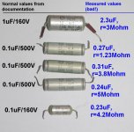
After all, I've measured all the capacitors from the PC board where the L15 tube is mounted, and I found 5 of them with problems (about two times bigger capacity than the real one).
I am talkin here about C22,C23 from the Wien oscillator; C12,C13,C17 and C19 from the electronic voltmeter.
I've replaced them with new units (polypropylene / 250...400V) after I've studied the schematic diagram to see if the operating voltage in that zone is supported.
Now, the amplitude remains constant in the 4/I pin, but it seems that I cannot calibrate the "S" anymore. Although I am obtaining 1400Hz in that point, the meter does not reach the calibration marker.
Yet another mistery to solve...
Any helping hand will be greatly appreciated!
Best regards,
Cezar
Hi all,
After all, I've measured all the capacitors from the PC board where the L15 tube is mounted, and I found 5 of them with problems (about two times bigger capacity than the real one).
I am talkin here about C22,C23 from the Wien oscillator; C12,C13,C17 and C19 from the electronic voltmeter.
I've replaced them with new units (polypropylene / 250...400V) after I've studied the schematic diagram to see if the operating voltage in that zone is supported.
Now, the amplitude remains constant in the 4/I pin, but it seems that I cannot calibrate the "S" anymore. Although I am obtaining 1400Hz in that point, the meter does not reach the calibration marker.
Yet another mistery to solve...
Any helping hand will be greatly appreciated!
Best regards,
Cezar
Attachments
Audio filters problems in L3-3 tube tester
Hi all,
I'm coming back to post the new problems that I am encountering while I am hardly trying to put the things alltogether at work, in order to obtain a valid system to measure the transconductance with my L3-3 (made in 1986).
As some of you, those that are happening to read this thread, probably saw my last post, I've said that I had some problems with the stability of the generated signal amplitude. After I replaced some bad capacitors in the Wien oscillator (C22 and C23 = 0.01uF), the output amplitude is stable.
Also, I've replaced C19 (0.1uF) in the audio filters stage; C19 is only a filter for the screen grid voltage of L14 (6J3P).
All ok until here... but, while I am trying to calibrate the meter using the 1400 Hz signal from the local (L15 = 6N3P tube) oscillator, the meter pointer does not getting higher than few divisions (max. 10).
However, if I'm adjusting the frequency pot (R155), the pointer reach the calibration mark around 1590 Hz, and is overscaling at more than 1600 Hz.
While I saw these problems, I've decided to study much closer the behaviour of those two audio filter stages. First of all, I've simulated them in LTSpice, using for their components the values given in the original Russian documentation.
Conclusions:
After I've did all of these, I've introduced again the L15 tube in the socket and after its warming, I adjusted R155 to obtain 1393 Hz at the point 4/I . The amplitude was anyway higher than that of the DDS.
BIG SURPRISE!
The meter pointer just reached the "10" division at maximum of the S calibration pot.
However, if I tried to rise the frequency generated by L15, I've noticed that the pointer is reaching the calibration marker at 1590 Hz and is overscaling on frequencies higher that 1600 Hz.
Well, this is something that if you'll kill me, I will not understand.
If someone here could have any idea that will help me, please post it.
I am attaching the following images:
Best regards,
Cezar
Hi all,
I'm coming back to post the new problems that I am encountering while I am hardly trying to put the things alltogether at work, in order to obtain a valid system to measure the transconductance with my L3-3 (made in 1986).
As some of you, those that are happening to read this thread, probably saw my last post, I've said that I had some problems with the stability of the generated signal amplitude. After I replaced some bad capacitors in the Wien oscillator (C22 and C23 = 0.01uF), the output amplitude is stable.
Also, I've replaced C19 (0.1uF) in the audio filters stage; C19 is only a filter for the screen grid voltage of L14 (6J3P).
All ok until here... but, while I am trying to calibrate the meter using the 1400 Hz signal from the local (L15 = 6N3P tube) oscillator, the meter pointer does not getting higher than few divisions (max. 10).
However, if I'm adjusting the frequency pot (R155), the pointer reach the calibration mark around 1590 Hz, and is overscaling at more than 1600 Hz.
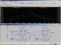
While I saw these problems, I've decided to study much closer the behaviour of those two audio filter stages. First of all, I've simulated them in LTSpice, using for their components the values given in the original Russian documentation.
Conclusions:
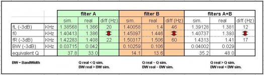
- when analysed as separate stages, the characteristics of the audio filters 1 and 2 are different. See the attached Excel table, where I resumed the results of the measurements, both in simulations and in reality.
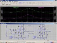
- when filters 1 & 2 are connected together, the output char. of the filter2 has the same profile with the output char. of the filter1 ! And both of them has a peak, of course, in the same point. You can see from the table that this point is at 1407 Hz in simulation and at 1393 Hz in reality (only 14 Hz difference...).
- With the L15 (6N3P) tube out from the socket and using an external AF generator (Wavetek DDS), I've picked up the characteristic of the entire audio filter stage (filter1 and filter2 connected together). The result has been clear (f0=1393 Hz and a bandwidth of 29Hz).
- using the S calibration pot (in the right side of the MEASURE/CALIBR. switch), the meter pointer reached without any problems the calibration marker (120).
After I've did all of these, I've introduced again the L15 tube in the socket and after its warming, I adjusted R155 to obtain 1393 Hz at the point 4/I . The amplitude was anyway higher than that of the DDS.
BIG SURPRISE!
The meter pointer just reached the "10" division at maximum of the S calibration pot.
However, if I tried to rise the frequency generated by L15, I've noticed that the pointer is reaching the calibration marker at 1590 Hz and is overscaling on frequencies higher that 1600 Hz.
Well, this is something that if you'll kill me, I will not understand.
If someone here could have any idea that will help me, please post it.
I am attaching the following images:
- filter 1 and filter 2 analysed as separate;
- filter 1 and filter 2 analysed as connected together;
- Excel table with the measurements results, in simulation and reality;
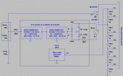
- a block diagram of the Wien oscillator and filters stage;
- the .asc (LTSpice) file containing the simulation of the Wien oscillator;
- the .asc file containing the simulation of the audio filters.
Best regards,
Cezar
Attachments
Thanks
Hi,
I would just like to say, that while I am in no position to be of any help to you in your endeavours, I wish you all the luck in the world and hope you continue as I have one of these testers and with your help I am learning how it works and hopefully how to keep it working from now on.
Thanks again.
If you have access to any spare parts for these, please let me know as I would be interested.
Klaatu
Hello Klaatu,[...]I wish you all the luck in the world and hope you continue as I have one of these testers and with your help I am learning how it works and hopefully how to keep it working from now on.
If you have access to any spare parts for these, please let me know as I would be interested.
I am a beginner in vacuum tube matters, but I like to take slowly and to dig into the problems step by step. My personal opinion: it's only up to everyone of us to build an equivalent hardware or better than L3-3. This was only a masterpiece of the russian technology of those times. In these days, there are many people that managed to build better machines than any of those dynosaurus like L3-3. You can find on the Internet some of such projects, but to make one means time and many efforts.
While I am not a big fan of russian tanks, I am smashing my head to revive this L3-3 only for the sake of hobby and because I am too lazy to build a similar machine right from the scratch.
However, I am planning to replace the electronic parts from my L3-3 with similar modules, but with classic semiconductors. Everything could be replaceable: the adjustable regulators, the Wien oscillator, the audio filters, etc.
Be sure that once I've started to deal with it, I will put all the informations that I'll obtain here and also on my own site (when all will be done, I'll publish the link to it).
I've landed here only about a week ago, and I've found few very kind members. Thanks to Greg Klemkosky and to Seraph for their explanations and time ! And also, as you've said, to anyone that will help to solve the problems regarding our L3-3 units!
Best regards,
Cezar
Audio filters problem resolved
Hi all,
The problem regarding the audio filters and Wien oscillator has been solved. Unfortunatelly, I've been cheated by my own frequency counter, that needs a higher level of the input signal.
After many measurements, a LED has been enlighted in my head and I tried to use my simple digital meter. Although it has a 4 digit frequency counter, it can measure signals up to 1MHz and I've checked it against my Wavetek DDS generator.
Well, the peak frequency encountered on the L3-3 meter, at the adjustment of the R155, has been exactly 1395 Hz .
After this check, I've applied the standard procedure for calibration, translated and described by Greg Klemkosky in his "Simplified Calibration Proceedures" document:
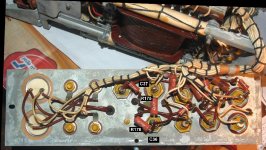
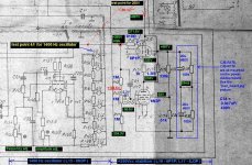
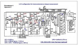
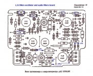
Just for the record and further references, I've measured the AF levels and the d.c. voltages on the important points of the board. You can see them on the attached images (schematic diagram and the location of the components). You will see there 5 checkpoints marked with blue color and the characters "CP1...CP5". In the bottom side of the schematic diagram, I've wrote the values of the audio levels that match the 0.45Vef level on the CP5 ( hole 4/I ).
Also, I've marked with red color, the d.c. voltages on every pin of the tubes. NOTE: the d.c. values are for a new set of tubes (NOS).
Hope that these informations will help .
Best regards,
Cezar
Hi all,
The problem regarding the audio filters and Wien oscillator has been solved. Unfortunatelly, I've been cheated by my own frequency counter, that needs a higher level of the input signal.
After many measurements, a LED has been enlighted in my head and I tried to use my simple digital meter. Although it has a 4 digit frequency counter, it can measure signals up to 1MHz and I've checked it against my Wavetek DDS generator.
Well, the peak frequency encountered on the L3-3 meter, at the adjustment of the R155, has been exactly 1395 Hz .
After this check, I've applied the standard procedure for calibration, translated and described by Greg Klemkosky in his "Simplified Calibration Proceedures" document:
So, this is it. Now, my L3-3 is measuring the transconductance very well.Calibration of the frequency of tuning measurer.
1. Connect a multi-meter red lead to 4/I of plug board and black lead to ground terminal. A meter that can read both voltage and frequency is preferred.
2. Place selector knob “isolation (ИЗОЛЯЦИЯ)” to the position “of pairs (ПАР)”, the selector knob “the parameters (ПАРАМЕТРЫ)” to the position “S”.
3. On the plug board insert pins into 20/I, 26/I, 40/II, 52/II.
4. Use resistors “amplitude (амплитуда) R157” and “frequency (частота) R155”, located on the left lateral panel of gauge, to attain 450 mV at the frequency of 1400 Hz +/- 50 Hz. (I generally calibrate the frequency to the peak frequency from the previous calibration). This may have to be done numerous times to get the proper voltage and frequency. When making the adjustments, be sure to use small incremental alternating adjustments to prevent the circuit from shutting down. If the circuit shuts down, back off the adjustments until readings return.
Just for the record and further references, I've measured the AF levels and the d.c. voltages on the important points of the board. You can see them on the attached images (schematic diagram and the location of the components). You will see there 5 checkpoints marked with blue color and the characters "CP1...CP5". In the bottom side of the schematic diagram, I've wrote the values of the audio levels that match the 0.45Vef level on the CP5 ( hole 4/I ).
Also, I've marked with red color, the d.c. voltages on every pin of the tubes. NOTE: the d.c. values are for a new set of tubes (NOS).
Hope that these informations will help .
Best regards,
Cezar
Attachments
Any docs to program L3-3 for another tubes ???
Hi all,
I'm working now to understand how to use the universal card to program L3-3 for measuring other tubes than those original russian from its wood box.
Does anyone has some translated form of the german documentation of Robert W. Berger? Or something similar that unveils this mistery ?
Thanks a lot,
Cezar
Measuring non-russian tubes with L3-3
Hi all,
In the last couple of days, I've studied much deeper the hardware and the "programming" of the L3-3 unit, also some supplemental extra docs .The most important is the "Quick Guide for the Russian tube tester L3-3" written by Robert W. Berger and published on Jogi's site.
While I don't understand German and there seems to be no translated version of this document, I've converted it from PDF to HTML page by page, and I've posted as it is here: Quick Guide for the Russian tube tester L3-3 (HTML German version). After that, I've used Google Translator to paste the URL of every page with text, and after a couple of hours, I've translated the document in a usable form. I will write a final translation, but I'm too busy for the moment.
Anyway, from this experience, I drew the following conclusions:
Best regards,
Cezar
Hi all,
In the last couple of days, I've studied much deeper the hardware and the "programming" of the L3-3 unit, also some supplemental extra docs .The most important is the "Quick Guide for the Russian tube tester L3-3" written by Robert W. Berger and published on Jogi's site.
While I don't understand German and there seems to be no translated version of this document, I've converted it from PDF to HTML page by page, and I've posted as it is here: Quick Guide for the Russian tube tester L3-3 (HTML German version). After that, I've used Google Translator to paste the URL of every page with text, and after a couple of hours, I've translated the document in a usable form. I will write a final translation, but I'm too busy for the moment.
Anyway, from this experience, I drew the following conclusions:
- in its original form, L3-3 was made to measure only the russian tubes;
- L3-3 could directly measure any non-russian tube that is 100% pin-to-pin compatible with the russian types (i.e. EL84 instead 6P14P);
- reading the hardware configuration from the schematic diagram, an adapting it with some tricks and compromises. For example, Robert W. Berger has used the socket no.11 to measure EF80, that has g2 wired to socket pin no.8 . In L3-3, this pin is connected to the line F9. The harware wiring of this line has no hole to allow connections to the Ug2 voltage supply. So, the trick was to use the hole 67/I to connect the F9 line (and , in this way, EF80/g2) to the Ua (anode) voltage supply. For this reason, when we will measure Ia, we will measure actually the sum of Ia and Ig2. I've verified this trick and is working fine, but if you want to know exactly the values of Ia and Ig2, you must make another tricks to measure them separately and then to calculate their sum and see if it matches the value displayed by the L3-3 meter. It's an interesting trick, but is somehow ... painful, or too laborious.
- using a new socket, properly connected to those nine lines from the L3-3 tester (F1...F9, that is marked on the russian test-cards with letters from A to I in the socket connections area). That's just my idea and I have not done it yet. But I intend to use for first socket no.14, that has all those nine lines (F1...F9 or A...I) wired to its contacts. Imagine an external socket mounted on a rigid metal
and connected by wires to the socket no.14.
That should work, of course, if you'll build and program the appropriate test card.
Best regards,
Cezar
- Home
- Design & Build
- Equipment & Tools
- Russian L3-3 tube tester