Grabbed this for next to nothing in perfect cosmetic condition and figured it an interesting enough piece to attempt to restore as a learning exercise.
The cord had been cut for reasons unknown. I figure with all those old caps in there it might be wise to do some replacements before powering it back up again.
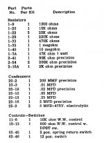
So, I went through the manual and began putting together a parts list.
Edit: Uploaded the parts list as an attachment rather than in-post as it was rendering strangely.
However, couple of problems I ran into:
1. Heathkit's manual doesn't specify voltages on the caps. From what I gather some of the caps are substantially overrated for their purpose.
In the unit these are the voltage ratings on the caps:
.2uf - 2x .1uf 400V
.01uf - 400V
.05uf - 600V
2uf - 200V
.25uf - 500V
One part in particular that a replacement is proving difficult to find is the two 8uf 475V Mallory Polar Electrolytics. Can't seem to find a replacement except at 8uf 450V and wondering if that's sufficient.
2. Heathkit says 1/2W Carbon Comp unless otherwise specified, but unsure if let's say a 1/2W CMF55 replacements are adequate, given that carbon comps from what I gather had higher voltage ratings.
Would I be better upping the resistor values to 1W? Metal oxide seem to have better voltage ratings than the metal films.
3. Curious what you all would recommend for the pots as well.
Slowly I'm learning (life is full these days), but always want to proceed with caution when high voltages are involved.
Full manual can be found here.
As always, grateful for any guidance / suggestions.
The cord had been cut for reasons unknown. I figure with all those old caps in there it might be wise to do some replacements before powering it back up again.
So, I went through the manual and began putting together a parts list.
Edit: Uploaded the parts list as an attachment rather than in-post as it was rendering strangely.
However, couple of problems I ran into:
1. Heathkit's manual doesn't specify voltages on the caps. From what I gather some of the caps are substantially overrated for their purpose.
In the unit these are the voltage ratings on the caps:
.2uf - 2x .1uf 400V
.01uf - 400V
.05uf - 600V
2uf - 200V
.25uf - 500V
One part in particular that a replacement is proving difficult to find is the two 8uf 475V Mallory Polar Electrolytics. Can't seem to find a replacement except at 8uf 450V and wondering if that's sufficient.
2. Heathkit says 1/2W Carbon Comp unless otherwise specified, but unsure if let's say a 1/2W CMF55 replacements are adequate, given that carbon comps from what I gather had higher voltage ratings.
Would I be better upping the resistor values to 1W? Metal oxide seem to have better voltage ratings than the metal films.
3. Curious what you all would recommend for the pots as well.
Slowly I'm learning (life is full these days), but always want to proceed with caution when high voltages are involved.
Full manual can be found here.
As always, grateful for any guidance / suggestions.
Attachments
First, odd things like 8uf caps were common 60 years ago, but not in recent decades. 10uf is just fine or even 22uf.
HAve you cleaned the pots?
The 0.05uf is from mains to chassis. I'd remove it and install a three wire grounded power cord myself.
I have no reason to second guess their voltage ratings. In my shop I'd be reaching for 630v film caps anyway.
I wouldn't sweat resistors, metal films would work just fine. If 1 watt makes you comfortable, the difference is just a few cents.
I have a similar Eico 950B I built some 55 years ago, I dearly love it, and it has seen use all these years. I recently passed it down to a younger tech who rebuilt it as you are doing, and it now sits on his bench.
You have found a really great old piece of gear that is useful as well. Many DMMs these days measure capacitance, but in repair work I am way more concerned with leakage, and these old testers will put actual voltage on the caps.
Manual and restorer-notes can be downloaded:
Heathkit C 3 Condenser Checker (manual) : Free Download, Borrow, and Streaming : Internet Archive
As the notes say, it begs for 3-pin conversion for user safety.
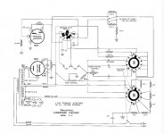
The 8uFd shown with 410V "could" get 466V on start-up. This assumes the 500V AC peaks at 707V DC, and the 47K vs 22K-string splits 1/3 to 2/3. Obviously when all is warm this cap should be nearer 410V. Even allowing higher wall-voltage today, I'd use a 450V if handy, though 500V is commonly available in guitar-amp parts. The 8uFd is not critical, use 10uFd, or even 4.7u or 22u if you have a heap. The two "8uFd" should probably be nominally the same, though wide mis-match won't do any harm.
I'm not following all the DC/AC relationships. Up to 0.05 (0.047), I'd use 400V rating. Having gone that far, it would only be a few bucks to do 600V throughout the film caps.
The 2uFd is noted "precision". It should be more accurate than you want to measure to. They probably gave you a 5% cap and claimed 10% on the whole thing. While you can buy better caps now, you can VERY cleaply buy digital meters of better precision. So I would treat this as a nostalgic folly and Good Working Tool, not any kind of micrometer theodolite chronometer. Buy a couple 2% 1uFd 600V caps and go for it.
Heathkit C 3 Condenser Checker (manual) : Free Download, Borrow, and Streaming : Internet Archive
As the notes say, it begs for 3-pin conversion for user safety.
The 8uFd shown with 410V "could" get 466V on start-up. This assumes the 500V AC peaks at 707V DC, and the 47K vs 22K-string splits 1/3 to 2/3. Obviously when all is warm this cap should be nearer 410V. Even allowing higher wall-voltage today, I'd use a 450V if handy, though 500V is commonly available in guitar-amp parts. The 8uFd is not critical, use 10uFd, or even 4.7u or 22u if you have a heap. The two "8uFd" should probably be nominally the same, though wide mis-match won't do any harm.
I'm not following all the DC/AC relationships. Up to 0.05 (0.047), I'd use 400V rating. Having gone that far, it would only be a few bucks to do 600V throughout the film caps.
The 2uFd is noted "precision". It should be more accurate than you want to measure to. They probably gave you a 5% cap and claimed 10% on the whole thing. While you can buy better caps now, you can VERY cleaply buy digital meters of better precision. So I would treat this as a nostalgic folly and Good Working Tool, not any kind of micrometer theodolite chronometer. Buy a couple 2% 1uFd 600V caps and go for it.
Last edited:
Yes I was not concerned as much with accuracy as voltage ratings on the caps and resistors.
As has been said this is more a curiosity and an interesting project. I’m not expecting to come out the other end with a piece of Keysight kit.
Thanks those restorer notes will come in quite handy. Lots of useful tidbits. I will of course update to a grounded IEC.
As has been said this is more a curiosity and an interesting project. I’m not expecting to come out the other end with a piece of Keysight kit.
Manual and restorer-notes can be downloaded:
Heathkit C 3 Condenser Checker (manual) : Free Download, Borrow, and Streaming : Internet ArchiveAs the notes say, it begs for 3-pin conversion for user safety.
Thanks those restorer notes will come in quite handy. Lots of useful tidbits. I will of course update to a grounded IEC.
How would you adapt to 3-pin when they are using the chassis for neutral? I’d like to avoid a complete requiring and new terminal strips if possible. I’ve always followed the rule bolt ground to chassis immediately. Could I put a power resistor and safety cap in between ground and the chassis?As the notes say, it begs for 3-pin conversion for user safety.
In the above I was referring to signal ground, neutral goes to the rectifier. Sorry, posting late at night.
Two other questions:
Also can someone indicate to me the required voltage rating of the .02uf (2x .01uf) precision cap? There’s no indication in the manual,
And in the notes the person indicates 2x 100K 5W should be used to shunt the 8uf electrolytics.
I am assuming this means place the resistor in parallel with each? Any clarification would be much appreciated.
Last edited:
Finally some progress:
My first attempt at a point to point design and it has been a great learning experience, especially with the assistance of the Heathkit guide. I was really impressed by the guides user friendliness.


Managed to shoehorn an IEC outlet in there, replaced all resistors and caps, cleaned the pots and switches.
Soaked and cleaned the knobs, front panel, etc. and will refinish the exterior case as it’s seen better days.
I may also look into a new 10K pot, or perhaps a new rectifier tube socket.
Then will finish the wiring up as per PRRs suggestions and make sure it follows the HealthKit manual.
Also made it through most of the modifications according to the addendum on the posted manual, which I might as well reprint below.
Should be a beauty inside and out when it’s done. I was lucky to come across this one with a pristine faceplate. Looked like it had sat undisturbed 40 years. For a cool $5 I felt pretty good about it.
Couple of questions still floating around in my head re:
If I have the shunting resistors across the electrolytics correctly (11 below)
Id like to add a fuse in case I did something dumb, but unsure what the appropriate value should be.
How I should wire everything when going from 2 prong to an IEC inlet (10 below)
I’m not sure if I understand the voltage divider resistor adjustment correctly, or if I’ve identified the correct resistor he is referencing below (4 below).
————————-
Notes on the Heathkit C-3 Condenser Checker
by Kenneth G. Gordon W7EKB
1) For the leakage tests, the voltages at the various points (25,150,250,350,450VDC.)are not very exact, even if the resistors are still within tolerance. The current through the voltage-divider string SHOULD be about 2.5 mA. (.0025 A). If that is so, and if all the resistors are within tolerance, then the calculated voltages will be about 25, 80, 135, 190, 245 VDC. Those resistors are always WAY out of tolerance, sometimes by several hundred percent though.
2) The 47k resistor,which is actually across the 1629, was found to be over 110K in the unit’s I’ve checked. This resistor sets a) the voltage across the 1629, and b) the total current in the string.
3) The filter capacitor closest to the diode only has the voltage across the 1629 on it,which varies, when you are measuring leakage, from a low of about 100 volts, to a high of about 200 volts, so a 475 volt or higher capacitor is not needed here. The other filter capacitor, however, has whatever voltage is left after the 1629’s requirements are met. The 1629 will operate properly with voltages as low as 100 VDC. Don’t go over 250 VDC though. Doing so will severely shorten the life of the eye tube.
4) Calculating the true resistor values that would give the correct voltages for the leakage test results gives us: 10 K, 50K, 40K, 40K, 40K. Adjust the true value of the “47 K” resistor at the “top” of the voltage- divider so that the actual current drawn by the string is 2.5 mA, and the voltages are accurate or slightly high at no load. The Leakage Test does NOT work unless the Power Factor switch is in the “Electrolytic” position.
5) The last 22k resistor between the voltage-divider string and the 450VDC switch connection is only a current limiter, so its true resistance value is not too important.
6) Replace all the capacitors, except the filters and the micas , with metallized film capacitors. The increase in accuracy and repeatability of the instrument is amazing! You will have to replace the filters with new electrolytics. The micas are usually OK, but you may want to test yours anyway, and replace those if they are out of tolerance.
7) All resistors in the voltage divider string should be replaced with 2 watt units. The power dropped by each resistor in the voltage-divider string will be around 0.25 watt.
8) Make sure the two resistors associated with the 1629 are within tolerance. If one is much lower in resistance than specified, the eye will not open fully, or could overlap when closed.
9) The maximum voltage at the 1629 should be subject to is 250VDC.Current should not be more than about 4 mA.
10) If the line cord is replaced by a three-wire grounded type, the repeatability of the instrument will be greatly improved, since that, according to the manual, can depend greatly on which way the plug is inserted in the wall socket. With a three-prong plug, it always goes in the same way.
11) If you shunt each power-supply filter cap with a 100 Kohm, 5 watt resistor, it will level out the power supply variations very noticeably, and make your leakage and other tests much more stable. This will also make the filter caps last a lot longer.
My first attempt at a point to point design and it has been a great learning experience, especially with the assistance of the Heathkit guide. I was really impressed by the guides user friendliness.
Managed to shoehorn an IEC outlet in there, replaced all resistors and caps, cleaned the pots and switches.
Soaked and cleaned the knobs, front panel, etc. and will refinish the exterior case as it’s seen better days.
I may also look into a new 10K pot, or perhaps a new rectifier tube socket.
Then will finish the wiring up as per PRRs suggestions and make sure it follows the HealthKit manual.
Also made it through most of the modifications according to the addendum on the posted manual, which I might as well reprint below.
Should be a beauty inside and out when it’s done. I was lucky to come across this one with a pristine faceplate. Looked like it had sat undisturbed 40 years. For a cool $5 I felt pretty good about it.
Couple of questions still floating around in my head re:
If I have the shunting resistors across the electrolytics correctly (11 below)
Id like to add a fuse in case I did something dumb, but unsure what the appropriate value should be.
How I should wire everything when going from 2 prong to an IEC inlet (10 below)
I’m not sure if I understand the voltage divider resistor adjustment correctly, or if I’ve identified the correct resistor he is referencing below (4 below).
————————-
Notes on the Heathkit C-3 Condenser Checker
by Kenneth G. Gordon W7EKB
1) For the leakage tests, the voltages at the various points (25,150,250,350,450VDC.)are not very exact, even if the resistors are still within tolerance. The current through the voltage-divider string SHOULD be about 2.5 mA. (.0025 A). If that is so, and if all the resistors are within tolerance, then the calculated voltages will be about 25, 80, 135, 190, 245 VDC. Those resistors are always WAY out of tolerance, sometimes by several hundred percent though.
2) The 47k resistor,which is actually across the 1629, was found to be over 110K in the unit’s I’ve checked. This resistor sets a) the voltage across the 1629, and b) the total current in the string.
3) The filter capacitor closest to the diode only has the voltage across the 1629 on it,which varies, when you are measuring leakage, from a low of about 100 volts, to a high of about 200 volts, so a 475 volt or higher capacitor is not needed here. The other filter capacitor, however, has whatever voltage is left after the 1629’s requirements are met. The 1629 will operate properly with voltages as low as 100 VDC. Don’t go over 250 VDC though. Doing so will severely shorten the life of the eye tube.
4) Calculating the true resistor values that would give the correct voltages for the leakage test results gives us: 10 K, 50K, 40K, 40K, 40K. Adjust the true value of the “47 K” resistor at the “top” of the voltage- divider so that the actual current drawn by the string is 2.5 mA, and the voltages are accurate or slightly high at no load. The Leakage Test does NOT work unless the Power Factor switch is in the “Electrolytic” position.
5) The last 22k resistor between the voltage-divider string and the 450VDC switch connection is only a current limiter, so its true resistance value is not too important.
6) Replace all the capacitors, except the filters and the micas , with metallized film capacitors. The increase in accuracy and repeatability of the instrument is amazing! You will have to replace the filters with new electrolytics. The micas are usually OK, but you may want to test yours anyway, and replace those if they are out of tolerance.
7) All resistors in the voltage divider string should be replaced with 2 watt units. The power dropped by each resistor in the voltage-divider string will be around 0.25 watt.
8) Make sure the two resistors associated with the 1629 are within tolerance. If one is much lower in resistance than specified, the eye will not open fully, or could overlap when closed.
9) The maximum voltage at the 1629 should be subject to is 250VDC.Current should not be more than about 4 mA.
10) If the line cord is replaced by a three-wire grounded type, the repeatability of the instrument will be greatly improved, since that, according to the manual, can depend greatly on which way the plug is inserted in the wall socket. With a three-prong plug, it always goes in the same way.
11) If you shunt each power-supply filter cap with a 100 Kohm, 5 watt resistor, it will level out the power supply variations very noticeably, and make your leakage and other tests much more stable. This will also make the filter caps last a lot longer.
Last edited:
Outcome fo the Heathkit C3 restoration
I am in the situation you were in last year i.e. I picked up one of these units and began restoration yesterday. I found the same manual and addendum to you that you did and I am mulling it over. I looked over the jpg that you posted and it appears that you substituted the resistor values as per the suggestions in item 4 of the addendum. How did that work out for you? Are the voltages closer to those labelled on the front panel leakage test function?
I am in the situation you were in last year i.e. I picked up one of these units and began restoration yesterday. I found the same manual and addendum to you that you did and I am mulling it over. I looked over the jpg that you posted and it appears that you substituted the resistor values as per the suggestions in item 4 of the addendum. How did that work out for you? Are the voltages closer to those labelled on the front panel leakage test function?
- Status
- This old topic is closed. If you want to reopen this topic, contact a moderator using the "Report Post" button.
- Home
- Design & Build
- Equipment & Tools
- Heathkit C3 Condenser Checker Restoration and Parts Recommendations