The raw oscillator output (max level) is 10V AC rms.
While it "can" be stable at ~~5V, the implied levels on the switch attenuator will be wrong.
Since I still don't see where you posted the set-up instructions you are following, I can't know if this detail is missing or you have missed it.
And yeah, there's no AC on the bias pot.
The Goal is to make 10V rms or 28V peak-to-peak without running into the 42V rail. There's a wide tolerance, but the circuit is simple and bias must be trimmed to the actual parts.
I agree: use a 'scope! I usually ran the Feedback way-up to make 14V-15V output. (No, this won't burn the internal meter.) At this point a slight tweak of Bias will cause clipping on the top or clipping on the bottom. Try to get a trace of clip on both sides. Or split the difference. Now it is sitting half-way up the 42V supply. (A little bit off exact-half because the amplifier is not symmetric.) Now turn the Feedback down to get 10.0V output. Done.
In the old days, we would then use the THD meter, because we might get one more 0.01% less THD with off-center bias (again because the amplifier is asymmetric). But in this 21st century, either the stock rough-trimmed IG-xx18 is clean enough, or you turn to the MANY "Improved --18" projects to hot-rod the amp and the AGC.
Update:
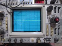
Going back thru the Adjustments section of the assembly manual and using a scope for the BIAS adjustment, I get no change from the displayed waveform in shape or amplitude. The Period shifts slightly when adjusting the BIAS pot full CW/CCW. I also am not getting a 10VPP output as measured on the scope. The panel meter indicates 10V. The waveform is clipped at top and bottom and does not change with the adjustment.
This is supposed to be a 1Khz waveform at the front panel output?
See attached photos.
Attachments
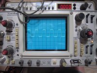
That's nowhere near a SINE.
The impulse is to trim the Feedback until it comes down out of clipping and looks like a Sine.
Yes, to set Bias you want "some" clipping. But not gross clipping.
There's other possible troubles and confusions. Did you verify the DC voltages in the sine oscillator?
The impulse is to trim the Feedback until it comes down out of clipping and looks like a Sine.
Yes, to set Bias you want "some" clipping. But not gross clipping.
There's other possible troubles and confusions. Did you verify the DC voltages in the sine oscillator?
Attachments
I know it's been a while but I had to shelve the repair of my IG-5218 due to work schedules and some home renovation projects. I now have the time to continue working on this guy and could use some guidance. Also, I recently acquired a IG-5218 Assembly manual and schematic for this unit that should be arriving any day now.
I had originally planned on re-capping the Power Supply and Wave Generator circuit boards and am now hoping doing this also helps fix the problems I'm having with this unit. Are there circuit locations on these two boards and elsewhere that will give me a good indication as to the health of the board components and where should I be expecting to see my first sine wave signal? This will be a work in progress and any help is appreciated.
Mark
Last edited:
It hasn't been mentioned yet, but the IG-5218 is merely the pre-assembled version of the Heathkit IG-18. So the circuitry is exactly the same, and the manuals and adjustment procedures are exactly the same, except that when working on an IG-5218, you don't have to worry about some bonehead assembly and soldering errors from 4 decades ago that might befall an IG-18 - it was assembled in a factory setting by professionals who did this all day long.
Best of luck getting it running! I haven't followed closely, but it may be useful to follow the procedure needed to adjust the forward gain so that the oscillator oscillates. All of the right parts could be in the box and yet the internal trims could be mis-adjusted so that the device does not operate properly. An IG-18 manual may help here, as this manual was designed to help a user to go from a box of parts to a working oscillator. You have a box of the right parts, so get the manual and do the startup and adjustment procedure and I bet it'll work. Heathkit was a master at DIY manuals.
EDIT: PRR's link above to the adjustment procedure is exactly what you need to do. If that does not work, come back with some questions, but honestly, that procedure should be comprehensive.
Last edited:
Monte McGuire;6032724 EDIT: PRR's link above to the adjustment procedure is exactly what you need to do. If that does not work said:Hi, Monte. Thanks for the response. See Post #24. I did start the steps in the procedure per PRR's recommendation. The attached waveform pix in Post #24 are what I got. So there is a problem somewhere and I am stymied. What next?
....there is a problem somewhere and I am stymied. What next?
Operation Manual
Check all DC voltages. Report any not-right. ...
Hi slipstream55,
The symmetrical clipping of the of the oscillator output suggests that the bias pot (R9) is set appropriately. Try adjusting the amplitude pot (R7) through its entire range. I believe amplitude should vary between no oscillation to the clipping waveform you posted in #24. It should be possible to adjust the amplitude to 10 Vrms.
Good luck!
- Status
- This old topic is closed. If you want to reopen this topic, contact a moderator using the "Report Post" button.
- Home
- Design & Build
- Equipment & Tools
- Heathkit IG-5218 Not Working, Where to Start Troubleshooting?