So I bought this volmeter & ammeter combination display:
Voltmeter Ammeter DC 100V 10A Red LED Panel Amp Dual Digital Volt Meter Gauge G | eBay
It arrived without any instructions, and doesn't look exactly like the picture. I intend to contact the vendor for instructions, but would like independent advice as well.
The volmeter side has 3 wires, red, black, yellow. I assume that black is ground, and red and yellow are positive supply and test voltage input, and verifying which is which should be pretty simple.
The ammeter side has 2 thick wires, red and black. I realize the picture shows 3 wires, and 2 of those thick bars (shunt?), but the model which arrived has only 2 wires and 1 bar.
I intend to use it as part of a regulated variable power supply.
I assume the ammeter is wired in series with the load under test? Regarding polarity, it it sufficient to wire it so that the red, positive, is connected to the positive of the power supply of the loop under test? Or is some other precaution required.
The current is sensed on the negative so everything is referenced (common) on the negative current output side. (so the sense amp sees a positive signal)but the model which arrived has only 2 wires and 1 bar.
AFAIK the internal circuits are powered by a +3.3 Vreg. which requires 4-30V max. so if your supply goes outside those limits say 0-35V you need to power it separately.
Re positive rail sense . I think if you power it from an independent small floating supply (say a 9V battery), you can hack it internally by cutting the shunt connection from the internal negative common..
Last edited:
The ammeter side has 2 thick wires, red and black. I realize the picture shows 3 wires,
and 2 of those thick bars (shunt?), but the model which arrived has only 2 wires and 1 bar.
The thick bars/bare wires are part of a single current sense resistor
that is mounted on the pcb for the ammeter.
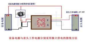
Here is the diagram. You may not have all the wires from the connector. Note, this diagram shows the large current shunt externally, it also can be placed on PCB internally (bare wire or 3 SMD resistors). The yellow wire is the voltage sense, the 2 black wires are common, E.g these are connected internally. ( the hack is finding their connection and removing a zero ohm SMD)
Attachments
Last edited:
- Status
- This old topic is closed. If you want to reopen this topic, contact a moderator using the "Report Post" button.