The cal routine worked quite well. Some of the settings were counter-intuitive. I had to set the source value to .075 to get a non-clipping source but after that all has been OK. With the RTX on 10V setting 5V gets 5.004V and that's with less than ideal metering. Are these cal settings stored with the soundcard selections?
Calibration
At present, you only can save or load the parameters of a specific sound card via the File pull-down menu -> Save Configuration or Load Configuration.
Thanks for testing.
Cheers,
E.
Perhaps at first sight, but ....The cal routine worked quite well. Some of the settings were counter-intuitive.
That's as expected with the RTX set at 10V and an initial cal factor of 'only' 1.0 (instead of 10.0).I had to set the source value to .075 to get a non-clipping source but after that all has been OK.
Not yet, but that would be a handy feature. On the other hand, what if the RTX setting has been changed to 1V? Then the cal. factors are invalid.With the RTX on 10V setting 5V gets 5.004V and that's with less than ideal metering. Are these cal settings stored with the soundcard selections?
At present, you only can save or load the parameters of a specific sound card via the File pull-down menu -> Save Configuration or Load Configuration.
Thanks for testing.
Cheers,
E.
Perhaps the noise is coming from my monitor which is refreshed at 60Hz.Looks like you have some 60 Hz PS noise getting in there, but your are in a 50 Hz power country. Also more higher harmonics? I'm sharing my settings in case they are useful.
Perhaps at first sight, but ....
That's as expected with the RTX set at 10V and an initial cal factor of 'only' 1.0 (instead of 10.0).
Not yet, but that would be a handy feature. On the other hand, what if the RTX setting has been changed to 1V? Then the cal. factors are invalid.
At present, you only can save or load the parameters of a specific sound card via the File pull-down menu -> Save Configuration or Load Configuration.
Thanks for testing.
Cheers,
E.
If you can implement reading from the RTX settings that would be compensated for. Meanwhle the RTX is very much an odd unit in this respect. Pretty much all soundcards have one setting (or maybe two for the pro cards, -10 and +4)
I wonder how the vertical refresh would be getting to the soundcard.
I'm already busy with the implementation of saving and loading the cal. factors, not only automatically, but also manually. In case of the latter one can use different filenames in order to distinguish the various settings.If you can implement reading from the RTX settings that would be compensated for. Meanwhle the RTX is very much an odd unit in this respect. Pretty much all soundcards have one setting (or maybe two for the pro cards, -10 and +4)
Me too. But when I lay the Lynx cable along the one to the monitor, I get more "grass" (6dB at 60Hz).I wonder how the vertical refresh would be getting to the soundcard.
Cheers,
E.
Calibration factors
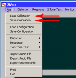
A new version (1.51.10) takes care of that. The cal. factors are automatically stored (and loaded) in a separate file with the name of the ASIO driver plus a .cal extension.
In case of sound cards with more than just one setting, you can save (or load) the cal file under another name via the file pull-down menu, see pic.
Cheers,
E.
Hi Demian,[...]Are these cal settings stored with the sound card selections?
A new version (1.51.10) takes care of that. The cal. factors are automatically stored (and loaded) in a separate file with the name of the ASIO driver plus a .cal extension.
In case of sound cards with more than just one setting, you can save (or load) the cal file under another name via the file pull-down menu, see pic.
Cheers,
E.
Attachments
These two spectra differ in the way how the individual FHT's of each record are summed together. In case of a incoherent spectrum, the power spectrum is simply based on averaging the power of the individual FHT's, while in case of the coherent spectrum, the phase of the fundamental and its harmonics is also taken into account. In this way the noise is averaged out (to a certain extent) and harmonics who were otherwise buried in noise become visible.Can you explain coherent spectrum vs. incoherent spectrum?
Cheers,
E.
version 1.53.1
Quote:
Originally Posted by 1audio
[...]Are these cal settings stored with the sound card selections?
Hi Demian,
A new version (1.51.10) takes care of that. The cal. factors are automatically stored (and loaded) in a separate file with the name of the ASIO driver plus a .cal extension.
In case of sound cards with more than just one setting, you can save (or load) the cal file under another any name via the file pull-down menu, see pic.
Version 1.51.12 contained some bugs* and is superseded version 1.53.1 In order to keep it simple and less prone to bugs, only the current cal. factors are loaded or stored automatically (in the ini file). But, of course, other sets of cal. factors can still be loaded or saved manually via the file menu (see post 568).
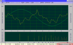
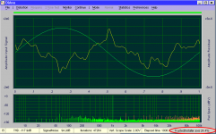
In the mean time I've added a few other features: An extension of the graphical presentation of the residual that is not only based on THD spectrum (as before), but also based on the (coherent) raw spectrum. Both residuals should be the same, and they are the same if the measurement is long enough to average out the effect of noise, see figures below.
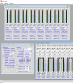
An extension of the "intruder alarm". If your machine is also busy with other tasks which occupies the CPU with more than 15%, the corner on the right bottom will light-up orange. Right clicking on it will show the amount of CPU usage (as before, see left pic). What new is that left clicking on it will show the name of the "intruder" (see right pic). Now the name of the culprit is known, one can silence that troublemaker. NB: Under W8 and W10 please run the program as administrator, otherwise the name of most system processes will not be captured by the intruder alarm.
Cheers,
E.
* New calibration factors were not saved under certain conditions.
Quote:
Originally Posted by 1audio
[...]Are these cal settings stored with the sound card selections?
Hi Demian,
Version 1.51.12 contained some bugs* and is superseded version 1.53.1 In order to keep it simple and less prone to bugs, only the current cal. factors are loaded or stored automatically (in the ini file). But, of course, other sets of cal. factors can still be loaded or saved manually via the file menu (see post 568).
In the mean time I've added a few other features: An extension of the graphical presentation of the residual that is not only based on THD spectrum (as before), but also based on the (coherent) raw spectrum. Both residuals should be the same, and they are the same if the measurement is long enough to average out the effect of noise, see figures below.
An extension of the "intruder alarm". If your machine is also busy with other tasks which occupies the CPU with more than 15%, the corner on the right bottom will light-up orange. Right clicking on it will show the amount of CPU usage (as before, see left pic). What new is that left clicking on it will show the name of the "intruder" (see right pic). Now the name of the culprit is known, one can silence that troublemaker. NB: Under W8 and W10 please run the program as administrator, otherwise the name of most system processes will not be captured by the intruder alarm.
Cheers,
E.
* New calibration factors were not saved under certain conditions.
Attachments
Last edited:
Just tried the latest version with the RTX. Its working quite well. The cal routine worked fine when I told it to save the calibration. it did not save a calibration the first time I tried for some reason.
How I set it up-
1) Unzip to a folder
2) Start the program and confirm its working.
3) Right click on the icon in the tray.
4) pin the icon
5) right click on icon
6) right click on "distortion analyzer"
7) left click on properties
8) Left click on advanced
9) select run as administrator to enable the info on who is stressing the PC.
On the statistics page for THD, Statistics 2, there are 3 THD numbers and a TNS number that are not clear. On one test I get a THD of -115 dB but that pages lists THD 511 which I don't understand. THD LPF is band limited THD w/o noise, THD+N is with noise. What is THS? And when it says tolerance what is it referring to?
Too many interesting numbers that I want to understand.
I really like to distortion analysis. This is the most useful of the software tools I have used. At this point, it would be great to have a way to use a passive notch in front and reconstruct. Would need an insertion loss curve to put in correction and some way to monitor the unnotched waveform to reference level and sync the reconstruction.
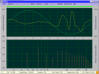
To explain why this display is so useful I'm uploading a plot from my Fluke 510A source. You can see the spectrum and the biggest harmonic is -120 dB (very good really). The upper waveform tells a lot more if you are trying to figure out what to fix/improve. It shows some compression on the negative part of the waveform. This makes sense since the amplitude monitor samples the peak negative of the wave. No other tool I have or have seen (except my Shibasoku) would give this insight.
Attachments
V1.53.1
Hi Demian,
THD-511 is simply the unfiltered THD. Why 511? That's the total number of harmonics of the so called "THD-spectrum". Remember, this FHT is a transform of the residual. That means, opposed to the so called "Raw-spectrum", that the frequency of thefirst second bin is the frequency of the fundamental itself, and frequency of the last bin 511 times higher (as the FHT size is 1024). It also means that some higher harmonics may lay beyond the Nyquist-frequency. With common audio ADC's these higher harmonics are meaningless as they are removed by the anti alias filter anyhow.
However, in case of this SAR-ADC for example and Frex has not put a LP filter in front of it, these higher harmonics are meaningful. But normally, it's better to exclude them from analysis by means of the built-in LP filter of the DiAna.
")
Cheers,
E.
Hi Demian,
Great!Just tried the latest version with the RTX.
I've tried to duplicate this error, but to no avail. Maybe the calibration file was saved in another directory. This might happen if you had not deleted the old ini file (while pointing to another directory) before running a new version. A few times it happened to me as well.Its working quite well. The cal routine worked fine when I told it to save the calibration. it did not save a calibration the first time I tried for some reason.
In order to run program as administrator I could have automated above steps, but that means I've to fiddle with the registry. That, however, would conflict with the philosophy of DiAna, as IMHO, a decent program should never pollute the registry. That's also the reason why it still makes use of an old fashioned ini file.How I set it up-
1) Unzip to a folder
2) Start the program and confirm its working.
3) Right click on the icon in the tray.
4) pin the icon
5) right click on icon
6) right click on "distortion analyzer"
7) left click on properties
8) Left click on advanced
9) select run as administrator to enable the info on who is stressing the PC.
TNS is an acronym for "Theoretical Noise Suppression" and is defined as 10logN, where N is the total number of averaged cycles (of the fundamental). Evidently, the larger the records size and the larger number of records processed, the lower the noise level of the THD spectrum. So this TNS figure simply predicts to what extent the noise level (i.e. the "grass" on the bottom of the spectrum) will be lowered.On the statistics page for THD, Statistics 2, there are 3 THD numbers and a TNS number that are not clear. On one test I get a THD of -115 dB but that pages lists THD 511 which I don't understand. THD LPF is band limited THD w/o noise, THD+N is with noise. What is TNS?
THD-511 is simply the unfiltered THD. Why 511? That's the total number of harmonics of the so called "THD-spectrum". Remember, this FHT is a transform of the residual. That means, opposed to the so called "Raw-spectrum", that the frequency of the
However, in case of this SAR-ADC for example and Frex has not put a LP filter in front of it, these higher harmonics are meaningful. But normally, it's better to exclude them from analysis by means of the built-in LP filter of the DiAna.
First, these tolerances are relative values. They are the standard deviation times 100% and divided by the mean value of that variable, except the offset tolerance (Ofs-X tol (%)). In this case it's divided by the amplitude of that channel (dividing by the mean offset value makes no sense, especially when this value is zero!).And when it says tolerance what is it referring to?
I hope above explanation will suffice.Too many interesting numbers that I want to understand.
Thank you.I really like to distortion analysis. This is the most useful of the software tools I have used.
As for 'notched' signals, please see next post.At this point, it would be great to have a way to use a passive notch in front and reconstruct. Would need an insertion loss curve to put in correction and some way to monitor the unnotched waveform to reference level and sync the reconstruction.
Cheers,
E.
Last edited:
notched fundamental
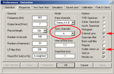
To overcome these troubles, one can use the frequency and phase info form the other "unnotched" channel. Therefore I've added a new field in the distortion preference menu (see below), where one can select the channel used for synchronization.
Note that (currently) this option is only available when the external sync option is enabled. Also note that this feature is still in development and needs more refinements
Cheers,
E.
Above remark prompt me to reveal another new feature, implemented on request of Keantoken. He also is using notched signals and trying to analyze them with DiAna. But.... since the program highly depends on data supplied by the amplitude, phase and offset detector (and when the external sync option is switched on, also on the frequency discriminator), a highly suppressed fundamental will invalidate these data. As a result, the outlier check will be triggered and data from the record concerned will be skipped.[...]
At this point, it would be great to have a way to use a passive notch in front and reconstruct. Would need an insertion loss curve to put in correction and some way to monitor the unnotched waveform to reference level and sync the reconstruction.
To overcome these troubles, one can use the frequency and phase info form the other "unnotched" channel. Therefore I've added a new field in the distortion preference menu (see below), where one can select the channel used for synchronization.
Note that (currently) this option is only available when the external sync option is enabled. Also note that this feature is still in development and needs more refinements
Cheers,
E.
Attachments
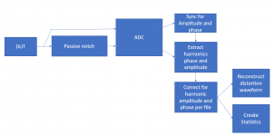
Here is a proposed model for using a notch filter with a two channel FFT. To get the accurate results you need a "gain phase" plot of the notch filter and maybe to interpolate the corrections for the specific harmonic frequencies. I think the Rohde and Schwartz UPV's do something like this but I'm not sure. Adding a make up amp after the notch filter could be accommodated as it would be flat gain correction. With this, it would be easy to get SOTA distortion measurement with a more generic sound card. You would still need an exceptional source.
Attachments
The pro version of DiAna has already the option to generate (and save) a gain/phase plot. So it would be relative easy to measure the characteristics of a notch filter and use the result to correct the "notched" residual. But such an extension of DiAna goes beyond the aims of the demo version. 
By the way, the pro version is also accommodated with a kind of "digital notch", that nullifies the distortion of the sound card as well. But to make use of it you need a high performance multiplexer and digital controlled attenuator in front of the ADC, way more complex than a simple notch filter.
(That's why those mysterious interval and dead time parameters in the distortion menu, and com port selection in the sound card menu).
Cheers,
E.
Well, almost everything, as I didn't expect how much time it would take (seven month already!) to answer questions, to implement new features and to resolve some bugs.Edmond you have thought of everything.
Cheers,
E.
pro version
As a matter of fact, I'm a bit reluctant to launch the pro version right now, as I'm afraid it will consume all my spare time. Why? See previous post.
Besides, it's better and more effective to write a comprehensive manual first and then launch the product. At the moment I can't oversee how much time it will take to get it ready. Perhaps next year?
Cheers,
E.
Hi Demian,And when will we be able to buy the pro version?
As a matter of fact, I'm a bit reluctant to launch the pro version right now, as I'm afraid it will consume all my spare time. Why? See previous post.
Besides, it's better and more effective to write a comprehensive manual first and then launch the product. At the moment I can't oversee how much time it will take to get it ready. Perhaps next year?
Cheers,
E.
- Home
- Design & Build
- Equipment & Tools
- DiAna, a software Distortion Analyzer