Remember the absolute accuracy is not important, after all it is matching or finding the differences or ratios. So using the same meter and range most measurement error terms are nulled.
Even then a 1% DMM in resistance function gives good enough accuracy to meet the same gain error budget using expensive 0.1% parts.
Don't understand your point. If 2 resistors both read 47.5k on a 3.5 meter, they are both between 47.45k and 47.54k according to the meter's precision. That can be a 1.9% difference.
EDIT: Oops, too hasty with the calculator, I see your point.
Last edited:
My reply could lead to another thread. One of my deepest pet peeves in the audiophile world - especially by those who can't/don't/won't actually pursue the math.
Basically “spec'ing ultra precision resistors” from the belief that “precision” ≡ improvement in sound. I've had (sheepishly) ridiculous arguments with highly opinionated people in this area, and the idea just beggars belief. And it persists.
Its like a religion. Founded on the patterns of tea leaves in teacups.
GoatGuy
You're not much into chip amps I see. You need that precision so that you can balance the load between chips. It's not religion. It's your calculator or simulator, if you have either of those
")
Seriously… be happy with your $5 (or in my case $29) 3½ digit multimeter.
I still have mine, well past breaking, there are no more stops on the range switch and I finally toasted a current sensing resistor. I still use it for everything (except current of course).
On the resistor precision thing, I agree, but would give some folks the benefit of the doubt if they think a resistor that could be manufactured to that precision starts with a better material which is generally true.
For those of you who have a VTVM from days of old, just past the end of the 1.5 volt scale there is a small dot or tiny circle. It is at 1.56 volts. That is the open circuit voltage of an old fashioned fresh carbon zinc cell.
That allowed easy calibration of the meter.
Now the scaling was often 1.5, 5, 15 etc. as 5% resistors were often used in the range switch that limited the accuracy on higher voltage scales.
So it was not just the low cost range doubling that influenced the design of early digital meters. It was also a bit of habit.
Thanks for the tip - ordered one!
//
Hi how much did you pay for the multimeter, I can only see "get quote" on their web page.
34450A Digital Multimeter, 5 1/2 Digit | Keysight (formerly Agilent’s Electronic Measurement)
ps. It's a pity it uses OLED, not good for static showing as they will risk suffering from burn in as the old CRT's.
A lot of what you get in good meters is protection from abuse. I stuffed up once and put my Fluke 87 across 240V Active-Neutral in 10A range. Popped the breaker for the lab, blew the 10A fuse in the meter and shortened my probes by a couple of millimetres, but that was it.
Good meters, Flukes.
Good meters, Flukes.
A lot of what you get in good meters is protection from abuse. I stuffed up once and put my Fluke 87 across 240V Active-Neutral in 10A range. Popped the breaker for the lab, blew the 10A fuse in the meter and shortened my probes by a couple of millimetres, but that was it.
Good meters, Flukes.
I of course never make mystakes.
But I do keep a few fuses for my fluke meters. Turns out they are much cheaper if you buy them as a fluke repair part than from a parts distributor selling the same size fuse. I do have to admit my high voltage voltmeter uses an analog meter as I don't really trust that there won't be a creep path to destroy a digital one. Also there is little possibility that the meter will stop reading due to a dead battery. Nice to know when it is safe to touch the circuit under test components.
Hi how much did you pay for the multimeter, I can only see "get quote" on their web page.
34450A Digital Multimeter, 5 1/2 Digit | Keysight (formerly Agilent’s Electronic Measurement)
ps. It's a pity it uses OLED, not good for static showing as they will risk suffering from burn in as the old CRT's.
I got a Paypal option etc... added one to the "basket"... the normal procedure...
Aha -I got mine from Banggood
//
You're not much into chip amps I see. You need that precision so that you can balance the load between chips. It's not religion. It's your calculator or simulator, if you have either of those
Hey there… since I'm willing (and able) to both learn and “do the math”, may I ask a favor? Post a schematic of a circuit (or a thread, or whatever) that shows how such precision current-sharing / load-sharing resistors are deployed.
I'm good with the math, so I'll spend the time thinking on this mathematically.
Thing tho is, it remains almost entirely untaught in our schools, whether pre-college or in-college, the difference between significance and precision. So many times (in journals, the news, Wikipedia, here at DIY and so on), do I see the problem.
The square-root of 2.0 Ω is 1.414214 Ω. Mmm… no! Its 1.4 Ω. The || average of a 47 kΩ and a 63 kΩ = 26.9182 kΩ? No… 27 kΩ would be just fine in the context. It takes knowing that both 47 and 63 are “standard values” in the 10% and 5% E–12 and E–24 nominal resistor lineup. Not 2% (E–48) or 1% (E–96) or 0.5% (E–192) or 0.1% (no E-designation). The 27 value is also in both the E–12 10% and E–24 5% resistor lineup.
Anyway… I look forward to see a schematic or linky that gets my thinking a-going. Don't like being a dinosaur!!!
GoatGuy
Hey there… since I'm willing (and able) to both learn and “do the math”, may I ask a favor? Post a schematic of a circuit (or a thread, or whatever) that shows how such precision current-sharing / load-sharing resistors are deployed.
I'm good with the math, so I'll spend the time thinking on this mathematically.GoatGuy
Well, the classic example I can think of are the circuits in Application Note 1192. Have at her. www.ti.com/lit/an/snaa021b/snaa021b.pdf
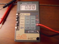
...Note the high quality test lead terminations on the meter
Oh, jiminy cricket!! And on a manual-range meter?? PLEASE glob some silicone goop on there. We don't want to lose you.
Yes, the Flukes are mostly idiot proof but I have blown up a 77 when discharging a CRT...the neg lead was connected to CRT earthing aquadag, the pos probe hanging open circuit.A lot of what you get in good meters is protection from abuse. I stuffed up once and put my Fluke 87 across 240V Active-Neutral in 10A range. Popped the breaker for the lab, blew the 10A fuse in the meter and shortened my probes by a couple of millimetres, but that was it.
Good meters, Flukes.
The risetime of the lightning discharge of the tube evidently induced into the probe leads enough to blow up the Fluke chip.
The best part of the 77 is the audible diode test when testing semis in a servicing environment....afaik there is nothing else with this feature.
Dan.
Come on you guys, I feel cheated now.
I bought some of this old stuff and they
only use 1, 3, 10 in their meter displays.
And on the 3, they don't even go full scale.
What where those two guys thinking in that
little Palo Alto garage. I feel so ripped off!
Oh for the Agilent 34450A...
Does that mean I should junk my HP34401A?
I bought some of this old stuff and they
only use 1, 3, 10 in their meter displays.
And on the 3, they don't even go full scale.
What where those two guys thinking in that
little Palo Alto garage. I feel so ripped off!
Oh for the Agilent 34450A...
Does that mean I should junk my HP34401A?
Last edited:
Well, the classic example I can think of are the circuits in Application Note 1192. Have at her. Error - TI.com
THANK you! Quite nice tech-note. You can always rely on TI to come up with outstanding theory notes.
Fortunately, they didn't actually "do the math". Their assumption in making the BA200 amplifier is that the use of precision parts is cheap enough to "do everywhere". For instance the 47 kΩ input resistor on the second-to-last page of the PDF is absolutely and completely unnecessary to have in 1% precision. it is just an input "ballast" resistor. 5%, 10% would be just fine.
Likewise (and I've been drinking enough today to not do the math outright), the math for the need for 0.1% precision gain resistors is overkill. In the right direction but still overkill. A much more rational solution would be to have a gain stage in front of the final stage having any-old resistors (maybe 2% or so) that do the voltage gain. Then the finals are unity-gain. Well matched "any" resistors would do just fine in helping balance output.
Also, the use of 1% current-sharing resistors (0.1 Ω) on the output is also a product of "well, they're cheap enough not to matter". Truth is, 5% ers are just fine too. 5% of 50 watts is 2.5 watt. Or if one's working in the current-sharing mode, then 5% of 20 volts (50 W into 8 Ω) is 1 volt. 55 vs 50 watts in differential output. "Who cares" territory. Tune-able with a bag of cheap 2 watt resistors and a 3½ digit volt-Ω meter.
Just saying.
A great application note example.
Without the usual TI-level-standard math.
GoatGuy
Thanks for the tip - ordered one!
//
Eventually arrived. Small. OK. Lost the screw to the battery compartment immediately - it's an M2,5 6mm
//
I got a new multimeter a few days ago
Can measure capacitance up to millifarads range
up to 9.999mF
and also frequency from 0.01hz to something around 0.99mhz
Also AC/DC amps volts range is not 1.999 instead its 9.999 range so I get much more accurate readings between 1v and 10v
Same with 20v range is now 99.99v range! much better! And still accurate.
The diode test feature also works with LED's on this one too! It was only 24$ from amazon free shipping no tax and takes two AAA batteries.
has autoranging and manual ranging function as well as a super bright LED light built in.
and a backlit display that stays on for about 15 to 30 seconds
Also current range can measure from 999.9mA from the 10A range up to 9.999A!! No more burning out the 500mA fuse
also has a 10A fuse with very low internal resistance (I used a set of heavier duty multimeter leads with clamps. and the voltage drop is even less. because I had them already from an older multimeter)
The current range seems very accurate I tested a 12v power supply with a 20mA 3v LED and 470ohm resistor and it came in at exactly 20.00mA right on the dot from a 12.00v power supply
Hate to break it to you, but more DMM counts is not an accuracy improvement>Also AC/DC amps volts range is not 1.999 instead its 9.999 range so I get much more accurate readings between 1v and 10v
It's still a crappy DMM with 0.5%+/-3 counts and like a 1999 meter you will still read 10.01V plus the last digit has a 3 count uncertainty, so it is only accurate to report 10.0 V or 3 significant digits on that reading (the range problem doesn't dissapear). You got the same resolution and accuracy as the harbor freight freebee when testing 1.5V alkaline cells or 12V car batteries.
Last edited:
It seems plenty accurate to me when I measure 12v. my charger and multimeter agrees with each other.
And my other two multimeters also agree with each other and my new 9.999 count meter.
at 12.00v they all read within the last digit within 0.001 of accuracy and for 12v within 0.01 of accuracy with each other.
the voltage doesnt flicker up and down either. it stays very consistant
also tested a few different AA batteries. my rechargeables fresh off charge were reading correctly
Same with a lithium ION 4.2v cell charged up to 4.2v exactly on the dot. 4.200v
- Status
- This old topic is closed. If you want to reopen this topic, contact a moderator using the "Report Post" button.
- Home
- Design & Build
- Equipment & Tools
- Why most multimeters range is 2v 20v 200v instead of 9v 99v and 999v