While I do have access to Audio Precision test equipment, many times it's much more convenient to do a sound-card based distortion measurement.
Here's a link to a youtube I made that shows an overview of how to do it, along with a schematic for a nice attenuator and limiter that you'll need to use on the input of the soundcard to make power amplifier measurements.
YouTube
Here's a link to a youtube I made that shows an overview of how to do it, along with a schematic for a nice attenuator and limiter that you'll need to use on the input of the soundcard to make power amplifier measurements.
YouTube
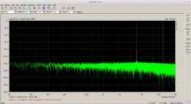
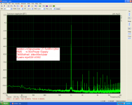
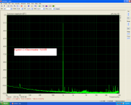
for the measurement shown, at 1 kHz, I used an oscillator of my own design that has about 2 PPM of distortion. It also has a 10K level control on the output, so there's not quantization noise issue.
As such, we're really only displaying the distortion of the A2D in the Behringer. so long as you don't overload it, its internal distortion is typically better than - 90 dB.
As such, we're really only displaying the distortion of the A2D in the Behringer. so long as you don't overload it, its internal distortion is typically better than - 90 dB.
Considering UCA 202 is a 16bit soundcard it is pretty good.
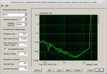
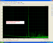
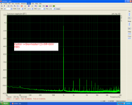
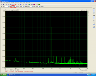
It is quite basic, all i/o is asymmetric. Looking for a replacement to measure bridged amp outputs I found the EMU-Tracker-Pre with symm inputs and 24bit resolution.
Dynamic range extends to about 110dB, loopback THD measurement at 1kHz drops to 0,0003% at medium levels.
It is my "poor man's AP"")
The first plot shows EMU202, the second one the EMU Tracker Pre
It is quite basic, all i/o is asymmetric. Looking for a replacement to measure bridged amp outputs I found the EMU-Tracker-Pre with symm inputs and 24bit resolution.
Dynamic range extends to about 110dB, loopback THD measurement at 1kHz drops to 0,0003% at medium levels.
It is my "poor man's AP"
The first plot shows EMU202, the second one the EMU Tracker Pre
Attachments
Last edited:
I also found this one...does anyone have experience with it?
ASUS Xonar U5 5.1-Channel USB Sound Card and Headphone XONAR U5
And...Joseph K...what mods did you make?...that one looks pretty darn good!
ASUS Xonar U5 5.1-Channel USB Sound Card and Headphone XONAR U5
And...Joseph K...what mods did you make?...that one looks pretty darn good!
Dear Dan,
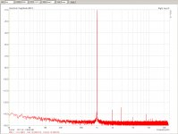
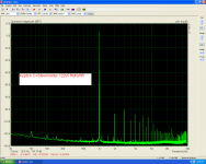
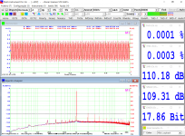
First of all, the EMU is using the AKM 5394A and is quite a good implementation by itself. The used njm2068D are very low noise, low distortion units. A bit slow, they are. So the opamp rolling to OPA1612-s did not bring much improvement in the basic frequency range but did bring down the distortion floor around 10kHz and above.
So the card started to become a 'tool', usable for testing the Myref composit amps.
Then the bypass capacitors around the ADC to organic polymers, more modern multilayer caps, removal of the output mute circuits in the dac - and lastly, what I could have known but tried only short ago: the AC coupling caps in the Dac output, usually bypassed by everyone, are essential for the Dac low distortion performance.. So the good old CS4398 is still capable of surprises.
The good thing is that this way the performance greatly stabilized through higher sample rates too; an optimal point is the 88khz sapling rate which is good enough for 20kHz distortion sweeps in STEPS and still gives a flat floor in the 0.00015% range.
The attach is done at 48kHz for bragging rights
Ps.: The card is multichannel, so there are three dac +three adc-s implemented. Two full channels can be freely used. They do perform slightly different. Choosing the best couple is another trick.
Ciao, George
Attachments
Last edited:
Thanks for your updates on the 1616M. The 1212M is very similar. Its possible to improve further if you have the complete circuit but its not published and the board is multilayer making that challenging. I have tried the LME49720's and they work but don't bring significant performance improvements. The cap upgrades may be more significant (not to mention replacing dead electrolytics, a common problem in the Emu stuff.)
Poor man's measure tools.
Esi-Julia pci.
In the first picture the Loop test.
The rest,measuring Real amplifiers.
Esi-Julia pci.
In the first picture the Loop test.
The rest,measuring Real amplifiers.
Attachments
Last edited:
I've updated this web-page to include a pdf file that describes how to build a switchable attenuator to use with a sound card. It enables using a soundcard to measure a power amp:
1 kHz Oscillator
1 kHz Oscillator
SoundblasterX G5 - poor loop-back results.
Perhaps someone knows why?
I wanted, as so many other, to be able to measure THD on my amplifier constructions. As they bring me no income, it had to be a low budget solution. I read about how a sound-card could be used with PC software. I managed to find my old Soundblaster Live 24 external card, and with more programs I managed to get loop-back results around 0.003% THD. Not bad for such an old card.
But, it would be nice to get a further 20dB precision. On specs, the up-to-date SoundblasterX G5 looked promising. 120DB THD was what I found in the technical specifications. Up to date drivers are available. I bought a SoundblasterX G5 and it sounded great with my headphones. With a loop-back coupling using the same loop-back cable as for the Live 24, I get around 0.03% THD!? (70db)!? An up to date sound-card with better specs than the old Live 24 actually performing 20dB worse!? Anything but what the specs indicated though the 120db are for DAC and ADC individually. I have used “Soundcard Oscilloscope” (uses only 16 bits) and “Arta”. They both agree on 0.03%. 0.03% is evidently useless for amplifier THD analysis.
Can anybody spot if I do something wrong here? I have tried both the line- and head-phone outputs. And, different cables. I use the line input. I have tried with different signal levels (0.03% is the lowest) Has anybody else experience with the G5 for THD analysis? If I cannot make the G5 perform better than that, I will use my Live 24 with a low-THD notch-filter in front. I am unexperienced in THD measurements.
Thanks for any replies.
First .003% is quite good performance. The best sound cards really can't do much better than about 10X that or .0003% (-110 dB) and then only when a lot of things have been carefully optimized.
Output and input level limit the THD. Best results are at around -10 to -20 dBFS.
THD and THD+N are different and THD+N is more difficult since any noise will limit the measurement.
You can use RMAA RightMark Audio Analyzer. Products. Audio Rightmark for loopback measurements with lots of details that can help diagnose the problems. They also have some instructions that may help optimize for measurements.
Thanks a lot for your reply. I agree, 0.003% is fine for the old Live 24. My surprise is that the G5 performs so poorly. I will try the RMAA software and see if I can get help to improvements.
If no G5 improvements, I will use the generator of the G5 (I hope Creative can at least make that part work well) and the ADC of the Live 24 with a T-notch filter. I intend to build the notch filter with ultra low THD LM4562s, foil capacitors, in a metallic enclosure with temperature stabilization and be modest with the filter steepness such that I only have 20-30dB damping.
Many thanks.
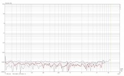
This is a loopback result for an Asus Xonar STXII replacing input ampops by LME49990.
Considering the costs, this audio card plus a good software is a very effective combo for a DIY guy.
The only thing that rests is to obtain a transparent input interface to protect the card against overloads. Even those offered here in GBs are a bit expensive, emho.
Best regards,
Considering the costs, this audio card plus a good software is a very effective combo for a DIY guy.
The only thing that rests is to obtain a transparent input interface to protect the card against overloads. Even those offered here in GBs are a bit expensive, emho.
Best regards,
Attachments
Last edited:
Not so long ago I made a posting concerning my new SoundBlasterX G5, bought for making THD audio measurements: http://www.diyaudio.com/forums/equi...nt-soundcard-arta-software-2.html#post5448294, posting #13.
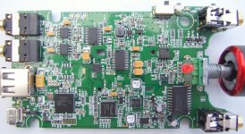
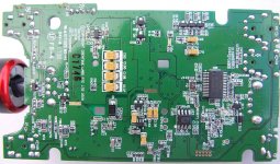
I carried on with testing of the loop-back performance and follow the advises I got, but continued having only disappointing results. Being a circuit-man and curious of nature, I finally decided to open the G5 casing and get a feeling with the electronics. Actually, the G5 is not that difficult to disassemble. Pull the volume knob off. Remove the friction rubber pad on the underside. Remove the four screws below the rubber pad. Pull the upper cover and lower cover loose from the middle frame holding the PCB. It's possible with delicate handling. That reveals the single PCB with SMD components on both sides. The digital part seems to work so I concentrated on the analog part.
Input buffer amplifiers for the ADC: TI M33078 operated from +5V only. ADC: Cirrus Logic CS5361 (24bit /114dB/192KHz). DAC: Cirrus Logic CS4398 (24bit /120dB/192KHz). DAC output filter and buffer: JRC NJM2114 operated from +/-5V. Headphone driver: TI TPA6120A2 operated from +/-10V. Step-up voltage booster: TI TPS65131 (bipolar output). Initial comments: The sound card is advertised as a 120dB unit. The DAC is up to that level but the ADC not fully.
The M33078 input buffer amplifiers have THD specs of 0.002% and a supply voltage range from 10V to 36V. Thus with 5V supply, the input amplifiers are supplied significantly below the minimum supply voltage. That they still function may be because they are particularly screened. The 0.002% THD is at +/-15V. At minimum supply voltage, the THD is significantly worse, and below minimum supply voltage even worse. The loop-back performance of 0.03% may be due to these input amplifiers and far less than what is indicated in the product description (based on the ADC itself).
The DAC output buffer and filter IC, the NJM2114, is specified for a supply voltage range of 6V to 44V. At +/-15V supply, the THD is specified to 0.0005%. Not a bad performance though below the 120dB of the DAC. But, again the actual THD performance is less good due to the reduced supply voltage. Not 120dB performance as indicated. The headphone TPA6120 amplifier chip is among the best monolithic headphone amplifiers. It is supplied with +/-10V from a TPS65131-based power converter. With a THD better than 100dB even at lowest specified supply voltage, this implementation is correct.
Present conclusions: At present, the actual analog part schematics have not been drawn up. Even without knowing the circuits, the reason for the mediocre THD performance in loop-back test is identified. The input buffer amplifier circuit is, from choice of OP-AMP and in particular a very low supply voltage, performing far below the 114dB of the ADC. Probably in the order of 0.03%. The choice for the DAC output buffer and filter design is better than for the input but not up to the standards of the DAC. The ADC and DAC ICs are of high quality but only with substantial redesign and rebuild of the analog audio circuits, the unit may be suited for THD test of audio gear. It will not be a trivial task due to the tiny components and the compact layout.
Attachments
Thanks a lot for your comments and you are right on the commercial pressure. What irritates me is not that the designers did not use more expensive solutions. Had they just used the +/- 10V already available also for the input amplifiers and the DAC output buffer/filter IC, the performance had been much better. They could have saved the -5V converter and eventually replaced the M33078s with NE5532s at the same price. The designers included many good components and then messed up in a few important places such that the result is far below what it could have been.
This is not atypical for the “China-boards” we buy and “pimp” in the Class D and Chip-Amps sections of this forum. Good intentions and a few serious mistakes. I could get the impression that this sound-card is an Asian product sold under a brand name. You are right, rationally I should find better sound-cards and forget about re-work. But, my brain has during the night figured out how I can manage to get access to the good ADC and very good DAC with an external circuitry. There is also a challenge in showing that I can at least do better.
FF
Last edited:
- Home
- Design & Build
- Equipment & Tools
- Distortion Measurement with Soundcard and ARTA software