Hi there,
This small project is essentially a power CCS, with some bells and whistles added to make it more convenient to use.
The bias current can be adjusted between 0 and 2A (2.5A), and with the internal supply, the maximum voltage drop across the inductor is 15V.
There is a provision for an external supply of up to 180V, allowing a resistive drop of up to ~170V.
A built-in meter displays the current in mA, and a monitoring output allows the connection of an external voltmeter.
A modulation input is also provided, in case the instrument is not used with an inductance-meter.
Attachments
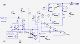
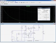
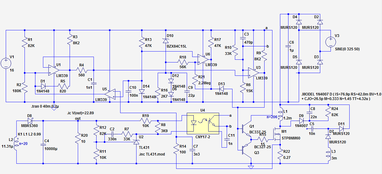
The DC feed needs to be as transparent as possible, to keep its influence on the L.U.T. as small as possible.
This means a SOTA CCS, servoed by an opamp and cascoded.
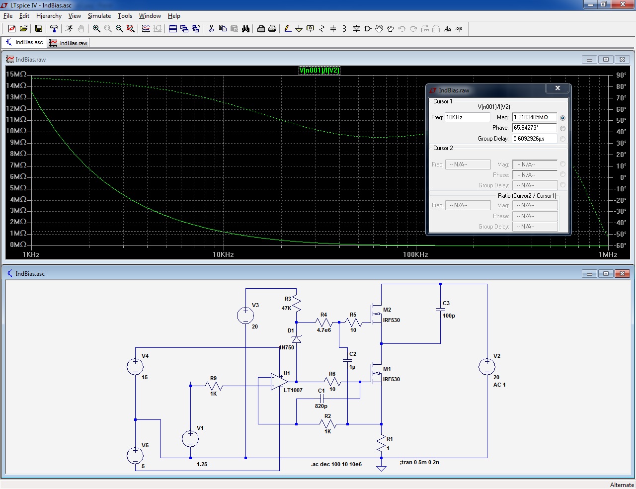
As the sim shows, the impedance @10kHz is ~1MΩ and this includes both the residual capacitance and parallel damping resistance:
The compensation scheme seems contrary to common sense, but that's what works in practice....
Of course, to retain the good characteristics of the base circuit, some guarding is necessary: between the MOSFet and heatsink, for the protection transil, etc. (C3 is not physically implemented, it models the drain to heatsink capacitance)
Ideally, even the wiring should also be guarded, to keep the additional capacitance in the pF range, but I didn't go that far.
The test instrument is connected to the L.U.T. via an isolating capacitor of large value (470µF).
This may be seen as less than ideal, because the ground of the test instrument is the positive rail, when the input ground is actually the ground.
With earthed instruments, this could be a recipe for disaster, which means the supply needs to be short-protected. Fortunately, it is, and it came handy on several occasions during the tests and debugging phase.
In principle, it would have been possible to keep a single ground, but this would require an ultra-clean supply: linear and sophisticated.
As I wanted to minimize the volume and footprint, this was ruled out.
The supply is an experimental PFC, which I used for the above-mentioned reasons, but don't particularly recommend, at least in this form. More on this later
This means a SOTA CCS, servoed by an opamp and cascoded.
As the sim shows, the impedance @10kHz is ~1MΩ and this includes both the residual capacitance and parallel damping resistance:
The compensation scheme seems contrary to common sense, but that's what works in practice....
Of course, to retain the good characteristics of the base circuit, some guarding is necessary: between the MOSFet and heatsink, for the protection transil, etc. (C3 is not physically implemented, it models the drain to heatsink capacitance)
Ideally, even the wiring should also be guarded, to keep the additional capacitance in the pF range, but I didn't go that far.
The test instrument is connected to the L.U.T. via an isolating capacitor of large value (470µF).
This may be seen as less than ideal, because the ground of the test instrument is the positive rail, when the input ground is actually the ground.
With earthed instruments, this could be a recipe for disaster, which means the supply needs to be short-protected. Fortunately, it is, and it came handy on several occasions during the tests and debugging phase.
In principle, it would have been possible to keep a single ground, but this would require an ultra-clean supply: linear and sophisticated.
As I wanted to minimize the volume and footprint, this was ruled out.
The supply is an experimental PFC, which I used for the above-mentioned reasons, but don't particularly recommend, at least in this form. More on this later
Attachments

The DC-blocking capacitor C9 is a necessary evil: it is required, because we don't want to subject the inductance analyzer to some arbitrary DC-component, but it poses several problems:
Even at 470µF, its impedance is not going to be negligibly low for lowish inductances measured at lowish frequencies, and going much higher wouldn't be practical, keeping in mind the 200V WV.
The workaround is to zero the inductance analyzer in circuit, with the L.U.T. replaced by a wire.
In case the negative value displayed is too large for the zero adjustment range, one can note the value, and subtract it from subsequent measurements.
Another issue is the transient conditions, and the voltage surges that can result at the measurement terminals.
Some (minimal) protection measures are included, like the 1Megohm discharge resistor, and the gas-discharge arrestor, but they aren't very effective: the resistor has a 470s time-constant with the capacitor, and 60V may already be sufficient to destroy any meter, but using more aggressive protections means would inevitably mean more parasitic damping and capacitance.
Therefore, caution is the best protection: the circuit is designed to wake-up in a soft, gentle and controlled manner, and if everything is properly and reliably connected at the time you hit the power switch, things will go smoothly.
The gain of the modulating input looks extremely low, but the purpose of the modulation is certainly not to approach 100%: normally, it will be used at a few percents at most, to explore the behavior of the core around a given induction.
3% of 2.5A is 75mA, requiring a hefty 7.5Vpp input, but in general the DC current will be set at a lower than maximal value, resulting in a more "normal" input modulation.
Overdriving the modulation could have violent and disastrous effects, which is why I made this condition difficult to reach under normal conditions
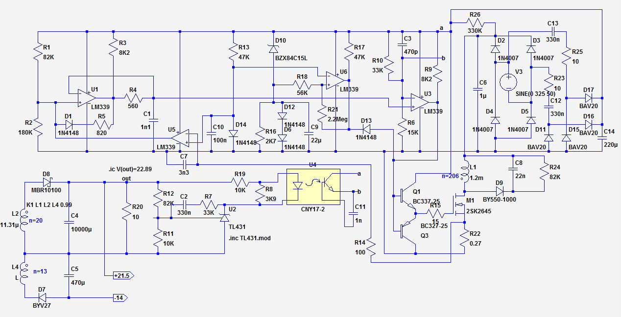
Initially, my intention was to use a conventional supply: 50Hz transformer, rectifier, filter (I even had everything ready), but I realized that the supply alone was going to be much bulkier than the rest, which is why I opted for a more compact solution.
As the 50Hz supply was not going to be regulated, I opted for an equivalent, switching solution: a single stage flyback PFC.
It is a flyback converter, operating in discontinuous mode and fed with the raw (unfiltered) rectified AC.
Because the main filter is situated at the output, and the servo loop is slower than the mains rate, the result is an "implicit" PFC.
The average output voltage is regulated, which is better than a conventional supply, but the 100Hz ripple remains the same; which is no problem, thanks to the performances of the super-CCS.
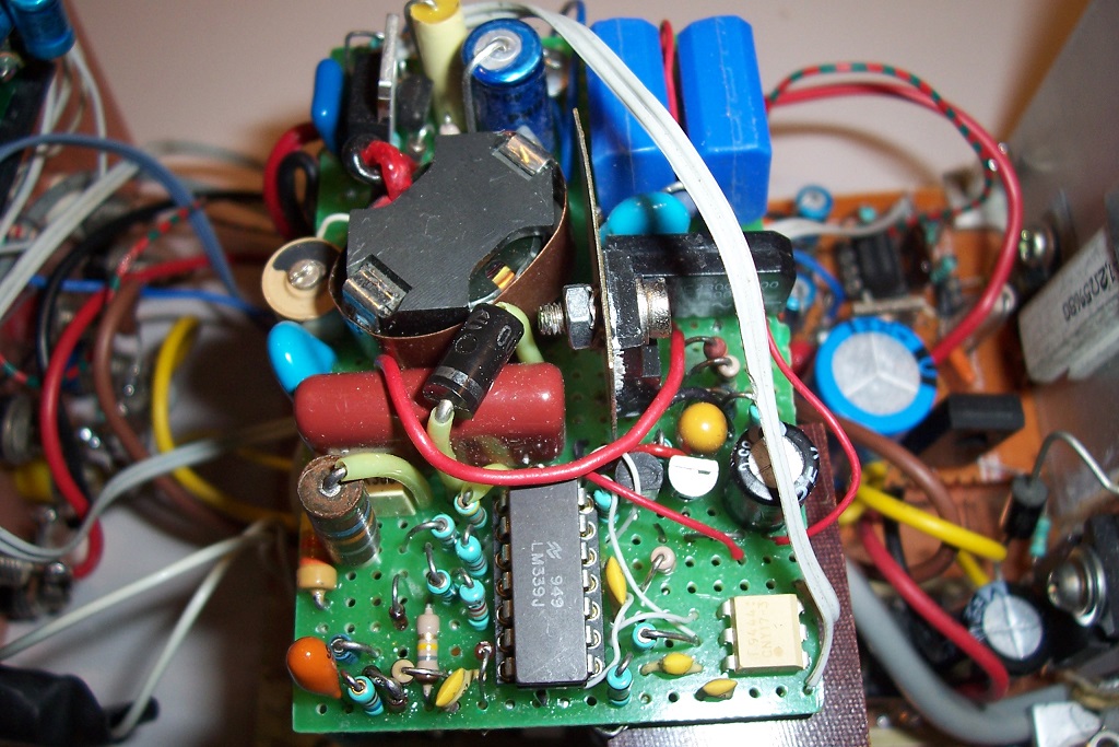
Such a supply is simple (the controller IC is just an humble LM339), but it does have some serious drawbacks: a poor utilization of the transformer and very high peak currents.
It would however be well suited to audio power tasks, which is why I will describe it in more details in the PSU section of the forum.
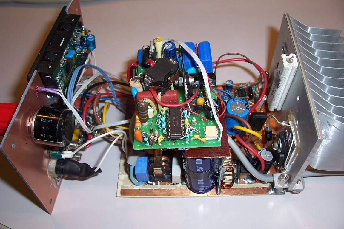
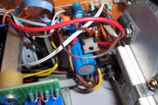
For metrological applications like here, it causes more headaches than anything else, in particular because of the very compact implementation of the instrument: everything is contained in barely more than 1 liter, and the high peak currents combined with the high sensitivity of the NE5534 to mag fields (something I just discovered) made the coexistence a nightmare.
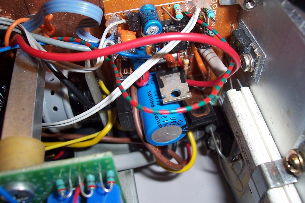
Something also worth mentioning is that the supply is somewhat under-dimensioned (always for compactness reasons): the transformer core is a RM8 core, N87 material, filled with copper to the point of bursting (quite literally, I had to hold it in a press while gluing it)and it overheats when operating at its max output of ~60W, but this has to be seen in perspective: the heatsink of the CCS is also much too small for continuous operation at such a power level: everything would melt-down after 10 minutes operation at the max power, but there is no way of sustaining such power levels in such a small space without forced cooling, something I hate...
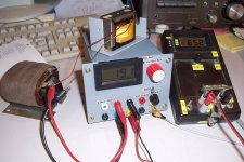
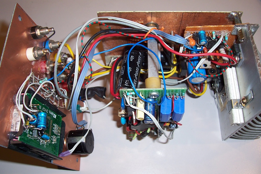
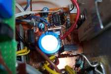
In the end, I fitted the RM8 with a heatsink:

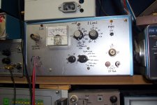
Here is the CCS part of the instrument:


Here is the simulable schematic of the supply:
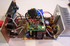
And the physical version:
As the 50Hz supply was not going to be regulated, I opted for an equivalent, switching solution: a single stage flyback PFC.
It is a flyback converter, operating in discontinuous mode and fed with the raw (unfiltered) rectified AC.
Because the main filter is situated at the output, and the servo loop is slower than the mains rate, the result is an "implicit" PFC.
The average output voltage is regulated, which is better than a conventional supply, but the 100Hz ripple remains the same; which is no problem, thanks to the performances of the super-CCS.
Such a supply is simple (the controller IC is just an humble LM339), but it does have some serious drawbacks: a poor utilization of the transformer and very high peak currents.
It would however be well suited to audio power tasks, which is why I will describe it in more details in the PSU section of the forum.
For metrological applications like here, it causes more headaches than anything else, in particular because of the very compact implementation of the instrument: everything is contained in barely more than 1 liter, and the high peak currents combined with the high sensitivity of the NE5534 to mag fields (something I just discovered) made the coexistence a nightmare.
Something also worth mentioning is that the supply is somewhat under-dimensioned (always for compactness reasons): the transformer core is a RM8 core, N87 material, filled with copper to the point of bursting (quite literally, I had to hold it in a press while gluing it)and it overheats when operating at its max output of ~60W, but this has to be seen in perspective: the heatsink of the CCS is also much too small for continuous operation at such a power level: everything would melt-down after 10 minutes operation at the max power, but there is no way of sustaining such power levels in such a small space without forced cooling, something I hate...
In the end, I fitted the RM8 with a heatsink:
Here is the CCS part of the instrument:
Here is the simulable schematic of the supply:
And the physical version:
Attachments


Hi SemperFi
I found this some time ago and built it with some additions. It is a simple clever Power Inductor tester. I added a power supply with 3 stages of Ilimit, Voltmeter & Trigger sync output.
This is a great tool for inductors & transformers and has not failed me.
Power inductor tester
Duke")
I found this some time ago and built it with some additions. It is a simple clever Power Inductor tester. I added a power supply with 3 stages of Ilimit, Voltmeter & Trigger sync output.
This is a great tool for inductors & transformers and has not failed me.
Power inductor tester
Duke
The main purpose is to measure inductors like filter chokes or SE transformers under their actual working conditions, but it can also be used to find the saturation current, however for that specific purpose, I had already built a dedicated tester, very similar in principle to the one shown by Duke, but a bit more sophisticated: it is adjustable for wide ranges, includes all the safety and limitation features, and has a built-in supply.So is this for testing chokes and finding saturation current? Looks like a cool project. But rather complex...?
It can also extract the losses under normalized conditions:
A very sensible decision.....but will skip the SMPS Elvee built.
Note that the pure CCS part of the project is not particularly complex, and it can be fed by a simple, unregulated 50/60Hz supply, which is the most sensible option
Attachments
- Status
- This old topic is closed. If you want to reopen this topic, contact a moderator using the "Report Post" button.
- Home
- Design & Build
- Equipment & Tools
- DC-Bias feed for inductors