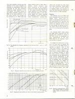
You have not provided very much information regarding exactly what you are doing. Assuming you are referring to a Bruel & Kjaer 2209 impulse sound level meter, this meter has built in selectable weighting (filtering) networks D, A, B, & C plus linear. Weighting networks alter the response of the instrument at different frequencies. Please refer to figure 11 below. Depending on just what you are measuring, you may not have any trouble with the instrument.
Attachments
Peak hold won't show the same as a steady RMS reading of a sine wave. Which mike is on it? Do you have a calibrator with known accuracy? There are two polarizing voltage options and a cal adjustment plus the 2209 has interchangeable scales (a lot of them for different applications as I remember).
Its all discrete so its pretty repairable but not easy. its also quite old. At its vintage some parts may just fail. The service manual is pretty complete and should have some troubleshooting help.
Its all discrete so its pretty repairable but not easy. its also quite old. At its vintage some parts may just fail. The service manual is pretty complete and should have some troubleshooting help.
lets start with some basic troubleshooting. This likn: http://exodus.poly.edu/~kurt/manuals/manuals/Other/BRUEL & KJAER 2209 Instruction.pdf to a manual will allow me to point to specifics. On page 41 of the PDF are directions for the calibration and which scales to use. It says to use the 2B scale and then adjust the level to 124 dB with the cal trimmer. The 1/2" to 1/4" adapter will reduce the sensitivity of the microphone some from the cal value in the spec due to the additional capacitance.
I think I saw your web site yesterday. If you have a sound interface and a PC you can do some quick troubleshooting from here with the PC to verify the electronics are working correctly. The Pistonphone typically has harmonic distortion below 1% which is remarkable for a mechanical system with a cam in the middle of it. If you load ARTA ARTA Software on the PC you should be able to read less than 1% THD with the harmonics quite clear. If the preamp is not working right you will see significant distortion or possibly clipping.
If you are trying to capture loud peaks (150 dB+) keep in mind the 4135 gets nonlinear around 160 dB. If you double the distance to the sound source the level will drop 6 dB.
Checking the peak hold on the SLM requires electronic connection to the input with some type of adapter and a suitable generator. I would use a function generator with tone burst and a scope to get it right. There are also calibrators (the GR Omnical http://www.ietlabs.com/pdf/Manuals/1986_im.pdf ) for this type of task but hard to find and expensive. The 2209 service manual should have specifics on the peak hold function. I think that's obsolete and something different for peak hold is in the current IEC specs for sound level meters.
Don't know of any free copies but these are possibly better than the originals: Other Manuals | ArtekManuals
I started the calibration and adjustment procedure
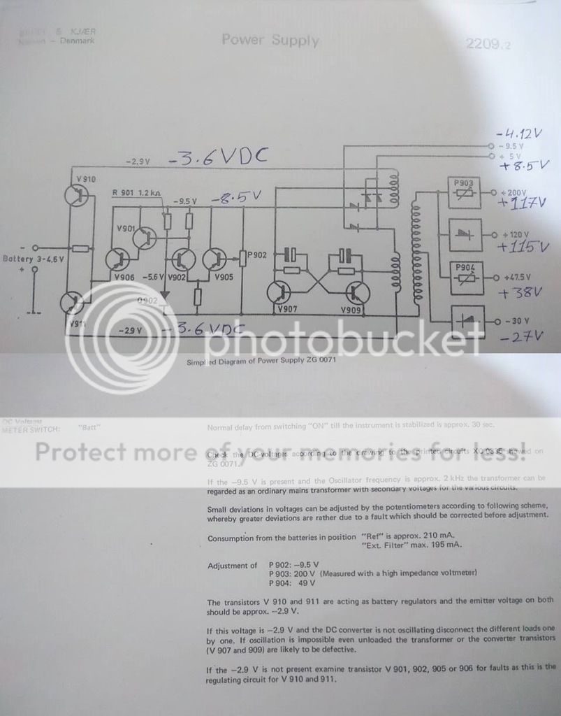
I checked the power supply. The voltage in the center transformer
is w/in spec as shown on my schematic attachment.
8.5 Vdc measured vs. 5V schematic.
-4.12 Vdc measured vs. -9.5V schematic.
-3.6 Vdc measured vs. -2.9V schematic.
Any Ideas, suggestions?
Cheers,
Sofyan
I checked the power supply. The voltage in the center transformer
is w/in spec as shown on my schematic attachment.
8.5 Vdc measured vs. 5V schematic.
-4.12 Vdc measured vs. -9.5V schematic.
-3.6 Vdc measured vs. -2.9V schematic.
Any Ideas, suggestions?

Cheers,
Sofyan
Modification in measurements
-8.5 Vdc measured vs. -9.5V schematic.
4.12 Vdc measured vs. +5V schematic.
[/URL][/IMG]
That seems to me to be close enough.


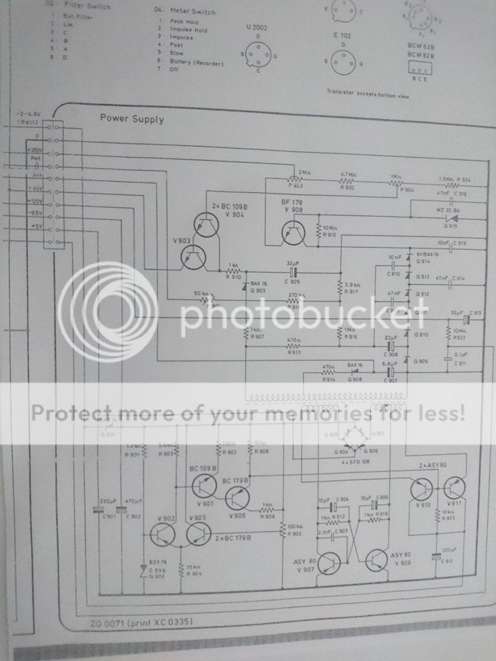
My first shotgun effort would be to replace the 40 year old electrolytics. Then check each transistor with a scope to see that they are all switching. If the doc's give you some input on the switching frequency you can get a sense for how much of the circuitry is working.
The 10 uF C904/C906 would be my first stop since they are part of the oscillator.
The bias supply for the microphone is at about 1/2 which would explain a -6 dB sensitivity.
The 10 uF C904/C906 would be my first stop since they are part of the oscillator.
The bias supply for the microphone is at about 1/2 which would explain a -6 dB sensitivity.
My first shotgun effort would be to replace the 40 year old electrolytics. Then check each transistor with a scope to see that they are all switching. If the doc's give you some input on the switching frequency you can get a sense for how much of the circuitry is working.
The 10 uF C904/C906 would be my first stop since they are part of the oscillator.
The bias supply for the microphone is at about 1/2 which would explain a -6 dB sensitivity.
Thanks a lot for your check up and advice.
I will do check all you mentioned and tell you back.
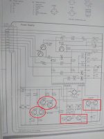
Usually the next step (probably should have been earlier) is to disconnect the loads to see if any of them are drawing too much power. It isn't easy on a dense portable instrument like this but it's the next troubleshooting step. However since the supply is all on one PCB it seems you may be able to disconnect it and measure what happens with no load. Typically with this type of circuit if any load draws too much it affects all the supplies.
- Status
- This old topic is closed. If you want to reopen this topic, contact a moderator using the "Report Post" button.
- Home
- Design & Build
- Equipment & Tools
- Help B&K 2209