Hi All,
I've made a small probe that has been designed specifically for measuring distortion locally in e.g. amplifier circuits (or lower-frequency noise on power supplies).
Its main feature is that it buffers the signal that is being measured with low distortion and with very little capacitance (less than 0.3 - 0.4 pF) and inductance thus only very marginally influencing the circuitry it is probing. It is AC coupled down to 0.4 Hz. Input impedance is quite high by use of a 1 Mohm resistor. I don't have equipment for measuring the bandwidth but I would guess that it is in the tens of MHz as the LME49990 is set-up as a buffer only.
My own use for the probe is as an interface between the circuitry being measured/probed and an AD7760 evaluation board that I use for distortion/FFT measurements - it appears to work well in this context.
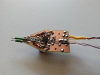
The circuitry is simple and based on an LME49990 (could be any other low THD+N opamp). It can be supplied from +/- 6VDC to +/- 18 VDC. There's an overload protection on the input, and on the output I've chosen to sacrifice just a bit of the noise spec to voltage divide the output so as to provide a failsafe overload protection (that is also not capacitive) towards the AD7760's input.
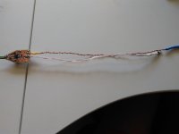
I've attached a picture of the probe - should anyone be interested I can post a schematic and a PCB layout (yet without Gerbers - for DIY make). Please note that I've used capacitors and diodes that I had so not everything is SMD.
Cheers,
Jesper
I've made a small probe that has been designed specifically for measuring distortion locally in e.g. amplifier circuits (or lower-frequency noise on power supplies).
Its main feature is that it buffers the signal that is being measured with low distortion and with very little capacitance (less than 0.3 - 0.4 pF) and inductance thus only very marginally influencing the circuitry it is probing. It is AC coupled down to 0.4 Hz. Input impedance is quite high by use of a 1 Mohm resistor. I don't have equipment for measuring the bandwidth but I would guess that it is in the tens of MHz as the LME49990 is set-up as a buffer only.
My own use for the probe is as an interface between the circuitry being measured/probed and an AD7760 evaluation board that I use for distortion/FFT measurements - it appears to work well in this context.
The circuitry is simple and based on an LME49990 (could be any other low THD+N opamp). It can be supplied from +/- 6VDC to +/- 18 VDC. There's an overload protection on the input, and on the output I've chosen to sacrifice just a bit of the noise spec to voltage divide the output so as to provide a failsafe overload protection (that is also not capacitive) towards the AD7760's input.
I've attached a picture of the probe - should anyone be interested I can post a schematic and a PCB layout (yet without Gerbers - for DIY make). Please note that I've used capacitors and diodes that I had so not everything is SMD.
Cheers,
Jesper
Attachments
Hi Patrick,
There's a 150 ohm resistor in series with the input (and 4*100 nF). Thus the practical capacitance (to my knowledge) is the capacitance from the input trace towards the underlying ground plane. However, I've removed the GND below the input trace so effectively the capacitance is very low (0805 one sided capacitance to my memory is 0.15 pF and then the "stray capacitance" from a trace-to-a-GND that is not just below the trace). So my guess would be 0.3 - 0.4 pF as seen from the circuitry being probed.
I do not know what the LME49990's input capacitance is, sorry.
Cheers,
Jesper
Hi PRR,
Thanks for your comment ... Yesterday, when EUVL posted his remark I didn't quite realize what he meant ... Yet I assume that what he is saying is that the opamp capacitance should be added to the input capacitance even if "hidden" from the input pins with the 150 ohm resistor. Always learning ...
Anyway, to hopefully clarify this, yesterday evening I simulated the LME49990 (buffer configuration) with a 1Mohm resistor in LTSpice. In this simulation the - 3 dB cutoff point is about 798 kHz which corresponds to an ~ 0.2 pF input capacitance for the LME49990 itself.
This morning I connected my oscilloscope's wave generator to the 1 Mohm resistor -> distortion probe -> the AD7760 and the level was down - 3dB around 30000 kHz. This corresponds to an appr. 5.5 pF capacitance. Which is higher than I had expected it would be ref. my post #1.
But taking into account what may just be learned here there are a couple of BAT83 diodes going from the input to the +/- supplies (~1.5 pF * 2) and a 0.6 mm trace with an ~1 cm length on 0.2 mm thickness FR4 PCB which is appr. 1.5 pF. So altogether it may add up to the appr. 5.5 pF.
 ... Which unfortunately sort of voids its purpose in my context ...
But I suppose it can be amended by moving the LME49990 closer to the input pins, eliminating the 1 cm trace and taking away the BAT83 diodes. Increasing the PSU supplies to +/- 18 VDC would then allow me to use it where I intend to use it. Hmmm ... things to ponder.
Cheers,
Jesper
Thanks for your comment ... Yesterday, when EUVL posted his remark I didn't quite realize what he meant ... Yet I assume that what he is saying is that the opamp capacitance should be added to the input capacitance even if "hidden" from the input pins with the 150 ohm resistor. Always learning ...
Anyway, to hopefully clarify this, yesterday evening I simulated the LME49990 (buffer configuration) with a 1Mohm resistor in LTSpice. In this simulation the - 3 dB cutoff point is about 798 kHz which corresponds to an ~ 0.2 pF input capacitance for the LME49990 itself.
This morning I connected my oscilloscope's wave generator to the 1 Mohm resistor -> distortion probe -> the AD7760 and the level was down - 3dB around 30000 kHz. This corresponds to an appr. 5.5 pF capacitance. Which is higher than I had expected it would be ref. my post #1.
But taking into account what may just be learned here there are a couple of BAT83 diodes going from the input to the +/- supplies (~1.5 pF * 2) and a 0.6 mm trace with an ~1 cm length on 0.2 mm thickness FR4 PCB which is appr. 1.5 pF. So altogether it may add up to the appr. 5.5 pF.
... Which unfortunately sort of voids its purpose in my context ... But I suppose it can be amended by moving the LME49990 closer to the input pins, eliminating the 1 cm trace and taking away the BAT83 diodes. Increasing the PSU supplies to +/- 18 VDC would then allow me to use it where I intend to use it. Hmmm ... things to ponder.
Cheers,
Jesper
When I want to measure noise or distortion precisely,I need to secure stable ground point.From your probe which has gnd adjacent to the input,I think you have the same consideration on that.But I usually can't find good gnd point near the measument point on the PCB.

High frequency clocks and voltage regulators usully have good gnd point,which is intentional from the first. But I sometimes need to check unpredicted point.Do you have good solutions about gnd point in such case ?
High frequency clocks and voltage regulators usully have good gnd point,which is intentional from the first. But I sometimes need to check unpredicted point.Do you have good solutions about gnd point in such case ?
@ xx3stksm: Hi ...
Yes, it would sound as if we are having similar considerations here. Anyway - I'd like to first stress that I'm not an expert here - but if it were me I probably would look into the layout relative to signal (return) current flow (i.e. where it flows and the levels) in order to find a low noise ground that is also at the voltage level of the point/node I would be measuring. I hope this make some sense?
What I mean is that if irrelevant current flows through a gnd point used for measurement then it may add distortion/noise, whereas a relevant gnd point may be stable relative to the place you are measuring ... In digital equipment I would look for the gnd return path and in analog circuitry I probably would try out where the measurements are most stable if it is not clear where the measured component's GND return path is.
And then I would use high impedance probes without side effects like high capacitances or impedances that drop very low at high frequencies. And a short GND wire on the probe.
Hope this is useful ;-)
Jesper
When I want to measure noise or distortion precisely,I need to secure stable ground point.From your probe which has gnd adjacent to the input,I think you have the same consideration on that.
Do you have good solutions about gnd point in such case ?
Yes, it would sound as if we are having similar considerations here. Anyway - I'd like to first stress that I'm not an expert here - but if it were me I probably would look into the layout relative to signal (return) current flow (i.e. where it flows and the levels) in order to find a low noise ground that is also at the voltage level of the point/node I would be measuring. I hope this make some sense?
What I mean is that if irrelevant current flows through a gnd point used for measurement then it may add distortion/noise, whereas a relevant gnd point may be stable relative to the place you are measuring ... In digital equipment I would look for the gnd return path and in analog circuitry I probably would try out where the measurements are most stable if it is not clear where the measured component's GND return path is.
And then I would use high impedance probes without side effects like high capacitances or impedances that drop very low at high frequencies. And a short GND wire on the probe.
Hope this is useful ;-)
Jesper
I've attached a picture of the probe - should anyone be interested I can post a schematic and a PCB layout (yet without Gerbers - for DIY make). Please note that I've used capacitors and diodes that I had so not everything is SMD.
Jesper
Yes, please post !
Thanks in advance !
> even if "hidden" from the input pins with the 150 ohm resistor
If you expect to measure near MegOhm impedance levels, 150r does not "hide" anything.
5p at 300KHz is around 100,000 Ohm impedance. So-what if the added resistor makes it 100,150r impedance?
However what you maybe really want to do is make the probe capacitance "less than" the capacitance of the circuit being probed. As you see, it is very difficult to get near 1pFd in a practical circuit. My old assumption was to expect any clot of wires to come near 30pFd. Small well-planned PCB nodes can do better. Yours did. It may be closer to 2pFd if you omit the protection diodes. Or bootstrap them so they follow the signal but WILL clamp LARGE currents when you poke some strong power node.
And adds distortion. The cap varying with voltage will modulate its impedance all of which adds distortion. Not important at the -60 dB level but probably below -100 dB. Same for the opamp.
One way to look at it is that 100K in series with a 10KHz source. Check how much the level changes as the input voltage swings around the target limits.
I agree you need a differential probe. You need a specific connection to the reference ground to know what the circuit is doing.
One way to look at it is that 100K in series with a 10KHz source. Check how much the level changes as the input voltage swings around the target limits.
I agree you need a differential probe. You need a specific connection to the reference ground to know what the circuit is doing.
And adds distortion. The cap varying with voltage will modulate its impedance all of which adds distortion. Not important at the -60 dB level but probably below -100 dB. Same for the opamp.
Yes but it all depends on the impedance level. At just a few k, you're probably good to -120dB. My experience.
Jan
> how does diode capacitance vary with the reverse voltage
Limiters Protect ADCs without Adding Harmonics
An externally hosted image should be here but it was not working when we last tested it.
Limiters Protect ADCs without Adding Harmonics
- Status
- This old topic is closed. If you want to reopen this topic, contact a moderator using the "Report Post" button.
- Home
- Design & Build
- Equipment & Tools
- Distortion measurement probe.