Hi all - & thanks for commenting/suggesting ;-)
@Samuel Groner: Hmmm, yes, a differential probe sounds like a good idea ... only it may be somewhat larger and from just briefly considering it - won't the input capacitances add up so that it doubles relative to the single-ended type ... ? Just in case I decide to go that way - would you use a regular instrumentation amplifier setup for this, or might you suggest a better one?
@LinuksGuru: Please confirm (comments here taken into consideration) that you are still interested in the current schematic/layout and I'd be pleased to post it ;-)
@PRR:
What I am really after is to be able to measure the circuit in question without influencing it (in any way). I realize this is illusory but would like to get close. And from reading yours, 1audio's, Jan's and gerhard's comments it seems that the non-linear capacitance from the input "safe-guard" diodes are the main culprit in this context (here I assume that the input capacitance of the LME49990 is <~ 1pF - or even ~ 0.2 pF as in the LTSpice simulation).
Given that I'd like to keep the size of the probe not larger than it is - is there a practical solution to the safe-guarding of the input that significantly reduces the capacitance (linear/non-linear) and doesn't deteriorate something else? An ad-hoc solution could be to omit the diodes entirely and then raise supply voltages to close to the +/- 19 VDC that the LME49990 will survive ... Or - is it likely to survive just a brief e.g. 0.5 second transient (input is ac coupled, yet at 0.4 Hz - 3 dBs) of input signal that goes maybe 8 volts beyond the PSU voltages?
@simon7000:
Thank you also for suggesting ... I admittedly am not much familiar with feedback theory/practice so here I would need you to be specific with your suggestion if I am to consider it further ...
Cheers,
Jesper
@Samuel Groner: Hmmm, yes, a differential probe sounds like a good idea ... only it may be somewhat larger and from just briefly considering it - won't the input capacitances add up so that it doubles relative to the single-ended type ... ? Just in case I decide to go that way - would you use a regular instrumentation amplifier setup for this, or might you suggest a better one?
@LinuksGuru: Please confirm (comments here taken into consideration) that you are still interested in the current schematic/layout and I'd be pleased to post it ;-)
@PRR:
Well, you are right. My main reasons for adding the resistor in series is to dampen/even out whatever capacitances & inductances might interact between the circuitry in question and the probe input circuitry. Probably it can be much lower and maybe even omitted.If you expect to measure near MegOhm impedance levels, 150r does not "hide" anything.
5p at 300KHz is around 100,000 Ohm impedance. So-what if the added resistor makes it 100,150r impedance?
However what you maybe really want to do is make the probe capacitance "less than" the capacitance of the circuit being probed. As you see, it is very difficult to get near 1pFd in a practical circuit.
What I am really after is to be able to measure the circuit in question without influencing it (in any way). I realize this is illusory but would like to get close. And from reading yours, 1audio's, Jan's and gerhard's comments it seems that the non-linear capacitance from the input "safe-guard" diodes are the main culprit in this context (here I assume that the input capacitance of the LME49990 is <~ 1pF - or even ~ 0.2 pF as in the LTSpice simulation).
Given that I'd like to keep the size of the probe not larger than it is - is there a practical solution to the safe-guarding of the input that significantly reduces the capacitance (linear/non-linear) and doesn't deteriorate something else? An ad-hoc solution could be to omit the diodes entirely and then raise supply voltages to close to the +/- 19 VDC that the LME49990 will survive ... Or - is it likely to survive just a brief e.g. 0.5 second transient (input is ac coupled, yet at 0.4 Hz - 3 dBs) of input signal that goes maybe 8 volts beyond the PSU voltages?
@simon7000:
I would suggest you add positive feedback to the input. Aim for .9 or so. That will raise the input impedance and lower the capacitive burden.
Thank you also for suggesting ... I admittedly am not much familiar with feedback theory/practice so here I would need you to be specific with your suggestion if I am to consider it further ...
Cheers,
Jesper
What I am really after is to be able to measure the circuit in question without influencing it (in any way). I realize this is illusory but would like to get close.
I'm not sure if you're not overcomplicating this. 99.99% of the time, measuring distortion in the audio frequency range means looking at the output of an amplifier. As we're using voltage signaling in audio, this is a low impedance node which easily drives a few pF, and much more if isolated by 100 Ohm (often already included in the circuit).
High-impedance nodes are rare in audio electronics. And if they occur (e.g. some intermediate nodes in discrete amplifiers), they usually are of no interest for distortion measurements.
Samuel
Agree with Samuel.
I have probed hi-Z points, but not with any hope of accuracy, just to see roughly what was happening.
Very few audio internal nodes run over a few Meg. A "X10" 'scope probe has small loading for amplitude or frequency.
ANY probing is likely to start, or kill, oscillations. Murphy's Law.
I have probed hi-Z points, but not with any hope of accuracy, just to see roughly what was happening.
Very few audio internal nodes run over a few Meg. A "X10" 'scope probe has small loading for amplitude or frequency.
ANY probing is likely to start, or kill, oscillations. Murphy's Law.
in a feedback amp those Hi-z points most likely will have much more distortion- the composite of all the distortion removed usually ends up at the hi-z nodes. )Speaking from experience). Often you can see the distortion with a scope. And the 100K input Z of a typical distortion analyzer won't load them.
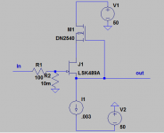
What I would do for this is something like a Cascoded FET buffer (shown). One with supply rails high enough to handle the peak voltages you may encounter.
What I would do for this is something like a Cascoded FET buffer (shown). One with supply rails high enough to handle the peak voltages you may encounter.
Attachments
Well, inputs from three people whom I know are quite experienced and well-versed in audio design & measurement - thank you!
@Samuel:
I may be so ... But I have for some time been curious about where the distortions actually appear - and part of the idea with this probe was to be able to measure where it actually happens (together with an AD7760 evaluation board). It may be that experience in time will show that I didn't need such a probe but I'd like to try it out ...
@PRR:
You actually are close to hitting the mark here ;-) ... I prefer my amplifiers wide bandwidth and sometime experience oscillations (although less so as time & hopefully learning improves). And since my oscilloscope probes are 17 pF in 10X setting, and the oscilloscope itself likely is not low distortion I decided on this probe as a way of possibly seeing more of how the circuitry would actually behave "without influence". But - I realize no influence is not possible ...
@1audio: Thanks again for your input and the schematic ... As it is I already have a couple of LSK189s (single LSK489) and the DN2540 so this could be an easy try-out ... Will just consider what to do ...
Cheers & thanks again,
Jesper
@Samuel:
I'm not sure if you're not overcomplicating this. 99.99% of the time, measuring distortion in the audio frequency range means looking at the output of an amplifier.
I may be so
... But I have for some time been curious about where the distortions actually appear - and part of the idea with this probe was to be able to measure where it actually happens (together with an AD7760 evaluation board). It may be that experience in time will show that I didn't need such a probe but I'd like to try it out ...@PRR:
ANY probing is likely to start, or kill, oscillations. Murphy's Law.
You actually are close to hitting the mark here ;-) ... I prefer my amplifiers wide bandwidth and sometime experience oscillations (although less so as time & hopefully learning improves). And since my oscilloscope probes are 17 pF in 10X setting, and the oscilloscope itself likely is not low distortion I decided on this probe as a way of possibly seeing more of how the circuitry would actually behave "without influence". But - I realize no influence is not possible ...
@1audio: Thanks again for your input and the schematic ... As it is I already have a couple of LSK189s (single LSK489) and the DN2540 so this could be an easy try-out ... Will just consider what to do ...
Cheers & thanks again,
Jesper
In a system subjected to global feedback, like typically most of the amplifiers, it will be very difficult to draw any hard conclusions from what you measure.....But I have for some time been curious about where the distortions actually appear - and part of the idea with this probe was to be able to measure where it actually happens
Hi Elvee:
That would be my guess as well - but as I don't really work with global feedback circuitries I reckoned the NGFB topologies would be "easier" (?) to investigate ...
Cheers,
Jesper
In a system subjected to global feedback, like typically most of the amplifiers, it will be very difficult to draw any hard conclusions from what you measure.....
That would be my guess as well - but as I don't really work with global feedback circuitries I reckoned the NGFB topologies would be "easier" (?) to investigate ...
Cheers,
Jesper
Last edited:
... But I have for some time been curious about where the distortions actually appear - and part of the idea with this probe was to be able to measure where it actually happens (together with an AD7760 evaluation board). It may be that experience in time will show that I didn't need such a probe but I'd like to try it out ...
While I applaud your effort, looking at the distortion of a single node in a complex circuit that uses any sort of larger loop feedback might be a misguided effort. Many of the internal nodes of a feedback circuit are only meaningful in the context of the entire circuit.
For example, if you look at some node which is meant to analyze and feed back error to the forward gain part of the circuit, you will find distortion there that is meant to be 'concentrated' so that it can be reduced by feedback. So, it's hard to interpret the nonlinearities at this one node as good or bad, when this node is perhaps just doing its job in taming the result of nonlinearities generated elsewhere. Perhaps the distortions concentrated here by the circuit topology exactly cancel the other 'forward path' distortions of the circuit, resulting in an extremely clean output?
I am a fan of symmetric, balanced circuits, and in that context, examining a single node outside of the context of it's dual symmetric node is misleading. In both of these examples, nonlinearities can be found in single nodes, but the problem is then interpreting how they affect the output of the circuit as a whole.
It's good to probe a circuit, and your device is very interesting, but I find that simulations are the easiest way to accurately probe the innards of a complex circuit without altering its behavior. Of course, the usual pitfalls of simulation can (and should) be brought up here, and I agree that a circuit should be prototyped to verify that it behaves as expected.
Still, when designing a circuit, I find it helpful to use a simulator to find these small details of how a circuit works, and see whether a circuit behaves the way I think it should. More often than I'd expect, a simulator will show me that the various circuit elements behave differently than I assumed, and that helps me to zero in on how the circuit actually works.
Another nice thing about a simulator is that it's easy to get it to show you the difference in voltage between two nodes, or the sum of two nodes, or any number of mathematical calculations based on the simulated data, something that's much harder to do with physical probes and conventional test gear.
Hi Monte,
Belated but nevertheless a brief feedback ... I am intuitively aware that trying to probe a node in a feedback circuitry may be less feasible. However, as I mainly work with relatively simple NGFB circuitries - and often/sometimes find that simulation models are either imprecise or actually not correct - I prefer to have the option of verifying a simulated circuitry, and layout, in practice.
Anyway, I think I've had some fine & useful feedback here so I may progress.
Cheers,
Jesper
- Status
- This old topic is closed. If you want to reopen this topic, contact a moderator using the "Report Post" button.
- Home
- Design & Build
- Equipment & Tools
- Distortion measurement probe.