Hi Mike,
Please note that most transistors suited for diff pairs have maximum collector currents of 50 mA to 100 mA. Testing should be done close to the actual current seen in the application. That would mean 1 mA to 2 mA tail current. I've been using 3 mA because the transistors settle faster. It might be instructive to try tail currents of 10 to 20 mA. The stock tester will support those current levels, but I didn't envision anyone would actually run the pairs that high. Keep an eye on the CCS pass transistor temperatures.
I think the "thermal cap" will work well. You might even be able to leave them on the PCB. That would be easier to deal with as there is a minimum of wires and just a pair of component parts, the tester and the heater. Power resistors are made that look like TO-220 transistors, and they would mount with a screw and grease to the aluminium block securely.
-Chris
used to be many dual monolithic devices in one package. What exist today as matched pair for audio ---- npn and/or pnp pair??
-Richard
I just bought 100 each of these pairs and none went over $20/100. Can't speak to the matching as I haven't tested any yet. Some are spec'd, some not. Unfortunately they're all SMD.
FMB2907
DMMT5401
DMMT5551
MBT2222
BCM857
BCM847
Mouser shows 226 npn pairs and 148 pnp pairs in stock, all SMD.
VBE mismatch in a differential pair ("long tailed pair") results in DC offset. National Semiconductor used to sell the LM194 / LM394 "Supermatch Pair" which had guaranteed, tiny amounts of VBE mismatch (0.05 millivolts!! app note below). Douglas Self's power amplifier book contains a detailed example, showing how VBE mismatch of the LTP transistors becomes nonzero DC offset at the loudspeaker output, when no DC servo is fitted.
VBE mismatch in a current mirror results in poor mirror performance (Iout not-equal-to Iin) and is one reason why most discrete current mirror circuit designs, use emitter degeneration resistors.
VBE mismatch in a TransLinear circuit, such as the Gilbert Gain Cell, also results in DC offsets.
VBE mismatch in a current mirror results in poor mirror performance (Iout not-equal-to Iin) and is one reason why most discrete current mirror circuit designs, use emitter degeneration resistors.
VBE mismatch in a TransLinear circuit, such as the Gilbert Gain Cell, also results in DC offsets.
Attachments
I'm experimenting with immersing the DUT in a beaker of (magnetically stirred) distilled water. Distilled water seems to be quite a poor conductor of electricity, both in theory and in practice. It's cheap to buy and easy to discard, unlike various oils.
Try this little experiment at home: connect a 6.5 digit bench DVM to a 1 megohm resistor and set to "OHMS". Note the meter reading (a) before immersing in distilled water; (b) while immersed. Calculate the equivalent parallel resistance of the water.
Looping back to this -- how/if at all are you protecting the transistor leads from electrochemical attack? Pure water is still pretty unkind to the bare metals, unless you're keeping the VCE well below 1V. Otherwise, I do like the idea.
Hi rsavas,
That might be true for devices on a single wafer, but it ain't so in normal use. I tried, because it is easier / faster. The beta test does work.
In real diff pair circuits, the Vbe will probably be close anyway, but at worst it would causes an offset of a couple mV. When Beta isn't equal, your shifts will be more than an order of magnitude greater.
The use of degeneration resistors allows you to vary the currents in different arms of a multi-element current source, or to force current sharing in diff pairs. They also make the transfer characteristic more linear in a diff pair.
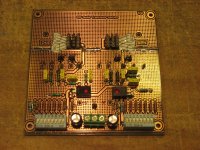
If you build a jig, you can test both as the jig also allows you to measure Vbe too. You can whip one together on perf board in 20 minutes or less, which is how long it took me to design, layout and build the first one on perf board. The only rub is to get tight matches on base and collector resistors. I ordered (and matched more tightly) 0.1% parts for mine. That was to be certain the jig wasn't throwing in errors of its own.
Either that, or you can argue the point endlessly, but building one and trying it for yourself might be easier and faster. I don't intend to debate something I tested for already.
-Chris
That might be true for devices on a single wafer, but it ain't so in normal use. I tried, because it is easier / faster. The beta test does work.
In real diff pair circuits, the Vbe will probably be close anyway, but at worst it would causes an offset of a couple mV. When Beta isn't equal, your shifts will be more than an order of magnitude greater.
The use of degeneration resistors allows you to vary the currents in different arms of a multi-element current source, or to force current sharing in diff pairs. They also make the transfer characteristic more linear in a diff pair.
If you build a jig, you can test both as the jig also allows you to measure Vbe too. You can whip one together on perf board in 20 minutes or less, which is how long it took me to design, layout and build the first one on perf board. The only rub is to get tight matches on base and collector resistors. I ordered (and matched more tightly) 0.1% parts for mine. That was to be certain the jig wasn't throwing in errors of its own.
Either that, or you can argue the point endlessly, but building one and trying it for yourself might be easier and faster. I don't intend to debate something I tested for already.
-Chris
Years ago a simple oven for crystals was published in Elektor.I think that this would be suitable for the job here.
Found it!
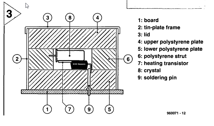
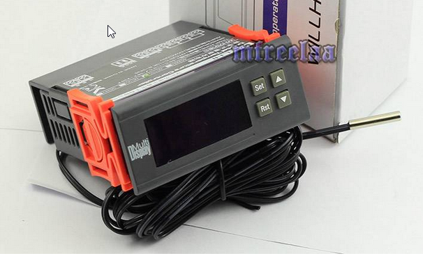
The circuit they describe to drive the heater is pretty cool, but I think one of these cheap e-bay thermostats will do wonderfully. 0.1F resolution.
Yeah, I don't think the exact oven design is applicable, but it confirms what we're finding here. The crystal oven is designed to keep just one device—the crystal—at a certain temperature. The transistor matcher has the additional requirement of keeping two devices at the same temperature. The heat-conductive die, surrounded by insulation seems to be the solution.
")
- Home
- Design & Build
- Equipment & Tools
- Matching transistors & measuring the results