In a recent discussion here it was mentioned that I needed to get a scope. Well I have one. The catch is I need to do a little work to put it back into service.
A very generous gentleman gave me a Tek 545B with CA plugin. He said that it does power up and show a dot on screen but no sweep. There are several tubes that are broken and have gone white. They are a 12AU6, 6DJ8, and this one that I can't read. It looks like 9C... or 90... on the envelope.


I have downloaded a manual for the scope and one for the CA unit and the sockets are marked so I should be able to figure it out.
Normally I would just replace all electrolytic caps (at least in PS) but there are lots of cans in there so am tempted to wait on that.


A very generous gentleman gave me a Tek 545B with CA plugin. He said that it does power up and show a dot on screen but no sweep. There are several tubes that are broken and have gone white. They are a 12AU6, 6DJ8, and this one that I can't read. It looks like 9C... or 90... on the envelope.
I have downloaded a manual for the scope and one for the CA unit and the sockets are marked so I should be able to figure it out.
Normally I would just replace all electrolytic caps (at least in PS) but there are lots of cans in there so am tempted to wait on that.
The tube type is labelled on the chassis right beside every socket.
Thank you I did later on figure out what it was. Tubes had already been removed and I hadn't located the socket for this one.
mike
BTW, I originally posted in the tubes forum thus the reference above to "a recent discussion here it was mentioned"
Resurrecting this old thread. Putting together a tube buy for the project. The three empty sockets I can find are for two 6922 (explains the 6DJ8) and a 8426. I presume that the 12AU6 must have come from that socket as they are pin compatible.
When I replace the tubes should I bring it up on a dim bulb apparatus? Gradual application of AC using variac advisable?
When I replace the tubes should I bring it up on a dim bulb apparatus? Gradual application of AC using variac advisable?
That would be a good plan.The 545 uses SS rectification,so a nice slow ramp-up with the Variac should help awaken the caps with minimal stress.
Do make sure that you peer into every nook and cranny (top and bottom) of that chassis;those TEK buggers hid tubes in the weirdest places.I had a 547 run me around in circles for an embarassing amount of time before I spotted an empty socket.
Do make sure that you peer into every nook and cranny (top and bottom) of that chassis;those TEK buggers hid tubes in the weirdest places.I had a 547 run me around in circles for an embarassing amount of time before I spotted an empty socket.
Funny story, Back in 1975 I bought a Tek 545 from a friend who worked for US Army Natick Labs. He bought it at auction and sold it to me for $15.00. It had been calibrated in 1974. It worked good for years. In 1982 I moved to Florida from Massachusetts and had to take a driver’s test with a 75 Chevy Nova 6cyl. They had one test called a panic stop where you stop as quickly as you can without locking up the breaks. The first time the rear brakes locked up and I failed, the second time they said that I did not stop quick enough. I then threw the 75Lbs Tek 545 in the trunk and passed! I eventually sold the scope for $50.00 in 1987 after it would not display a trace for 20 minutes after it was turned on.
The 545B is still my main scope, used weekly or more often. I have fancier scopes, but the 545B has nice big knobs and takes the high gain differential plug-in, the 1A7A. Mine has been very reliable since I got it maybe 30 years ago. A problem it had was every now and then the trace would slowly fade out, usually at some critical time, say when demonstrating something to someone. Many people claimed it was caused by a faulty HV transformer. Mine turned out to be a paper cap across the HV transformer. It's been perfect ever since I changed it out.
I finally got around to replacing those broken tubes. The dim bulb wasn't allowing enough voltage through for it to start it up so I took the chance and plugged it in directly.
I turned it on and got a faint vertical line part way up the crt but after a minute or less I heard a snap that could have been arcing or a relay so I shut it off and removed the right side panel and turned it back on. I got a bit of a scare. When I heard the snap this little guy suddenly glowed bright orange!

So I switched it off and lookup the tube at Frank's. Turns out it is a gas VR tube so I gather the scary glow is proper.
I turned it on and got a faint vertical line part way up the crt but after a minute or less I heard a snap that could have been arcing or a relay so I shut it off and removed the right side panel and turned it back on. I got a bit of a scare. When I heard the snap this little guy suddenly glowed bright orange!
So I switched it off and lookup the tube at Frank's. Turns out it is a gas VR tube so I gather the scary glow is proper.
When I let it finish coming up I get a bright horizontal line approx. 1/4 of the width which slowly traverses from bottom to top disappearing off the top apparently forever. So the CRT seems to be working. I have no probes or even a BNC cable so I am not sure I can do much more until I have a way to present an input but I will entertain any suggestions.

> I have no probes or even a BNC cable so I am not sure I can do much more until I have a way to present an input
Stick one end of a 1K 1/2W resistor in the middle of the BNC. Not a great connection, but it will not damage the BNC. Put your finger on that, you can read room-hum (after you work out sweep and triggering). Get red and green clip-leads, you can do about anything audio. (Hook the resistor with a rubber-band to keep contact in the BNC.)
Stick one end of a 1K 1/2W resistor in the middle of the BNC. Not a great connection, but it will not damage the BNC. Put your finger on that, you can read room-hum (after you work out sweep and triggering). Get red and green clip-leads, you can do about anything audio. (Hook the resistor with a rubber-band to keep contact in the BNC.)
One good thing is that pretty complete documentation is available. On my phone I have a pdf of the manuals for the "A" model and "B"models (mine is B) and the CA input plugin modual that include calibration, troubleshooting, and schematics information.
At this point I get a brief spot when the relay kicks in before it flys off screen. There is a little smudgy "tail" that corrisponds to the horizontal position of the beam. If I turn the horizontal possition all the way to the right the tail appears on the left side of the screen.
So we have excess deflection in both axes. I imagine the first step should be to check the voltages in the "low" voltage supply. I don't have a KV meter to check the high voltage supply. If that checks out I suppose the horizontal amplifier is the next thing to check.
Here you can see the tail.

I wonder if it is possible to run with the plugin removed to see if the vertical problem is in it or the builtin vertical amplifier.
At this point I get a brief spot when the relay kicks in before it flys off screen. There is a little smudgy "tail" that corrisponds to the horizontal position of the beam. If I turn the horizontal possition all the way to the right the tail appears on the left side of the screen.
So we have excess deflection in both axes. I imagine the first step should be to check the voltages in the "low" voltage supply. I don't have a KV meter to check the high voltage supply. If that checks out I suppose the horizontal amplifier is the next thing to check.
Here you can see the tail.
I wonder if it is possible to run with the plugin removed to see if the vertical problem is in it or the builtin vertical amplifier.
As Mama taught me I must fess up to the stupid. Going to check the LV supply I switched my meter probe from alligator clip to small tip so I could get into the ceramic strips. Unfortunately I plugged it into the 10A socket rather than the V+. As you can imagine I woke up when I tried to measure the first voltage. Putting the probe in the right socket (and testing that the meter still functions) I can measure no Voltage at any LV test points.
I thought that I might have blown a fuse but according to the manual there is only one fuse (for either 120 or 220V) and the tubes still light, crt still lights up, fan and relay all operate so certainly I have not blown the main fuse. I thought to check anyway but after loosening the screws the fuse cover won't come off. Must be some trick to it.
I guess I need to troubleshoot the LV supply but apparently that is one schematic that is not in the manual.
A quick guess here- The HV is OK or the traces would spread across the screen(Lower HV give the deflection more control). I believe they are all regulated and refer to one as a master. The manual will walk you through the supply checking and adjustment. Going high would suggest either a resistor changing value or some load pulling too much and everything overreacting. Possibly a supply cap failing. Check the supplies with the plugin removed.
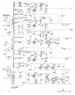
I found a manual online (also "old school" in the DJVU format, something I have not seen in years). The sole adjustment is for the -150V supply. Everything else references that. So step 1 is to adjust it. The snap you heard was the delayed power on for the supplies. One of the reasons these last so long is that the supplies don't start until the filaments are fully warmed up. The supply is as complex as a solid state supply except for only NPN equivalent devices. Everything regulated. You should see why it's so far out of regulation. There are probably some other issues hiding in there.
I have had a number of the tube scopes. The cost of the power to run them became prohibitive here in California. Usually, once they are running you can ignore them for years.
Two good references for Tek: TekScopes@groups.io | Home and 545 - TekWiki
- Status
- This old topic is closed. If you want to reopen this topic, contact a moderator using the "Report Post" button.
- Home
- Design & Build
- Equipment & Tools
- Scope on the bench ready for refurb.