I'm partial to Thurlby power supplies. Most-all the lab benches I've worked at professionally over the years had either a Thurlby lab supply or a newer Thurlby-Thandar (TTi) one.
I set up a lab back in Sydney perhaps ten years ago, and bought Agilent E3642s, thinking HP, gotta be good. After the second one failed inexplicably I stole some old Thurlby supplies from a neighbouring lab and went back to them. I've never known a Thurlby supply to fail. Sure, plenty of things connected to them have lost their magic smoke, but the supplies themselves have just kept on going.
Anyway, the PL320 is a bog-basic 2A, 30V supply. The PL154 is similarly a 4A, 15V supply. Totally linear, and no switching between taps. Just an overspecced transformer, a pile of 2N3055s on some heatsinks, and a pair of reasonably nice LED displays. Newer ones went to LCD and became unreadable. They eventually went back to LEDs.
They have remote sense, and they have a DC enable switch, which is useful for setting current before you turn the load on.
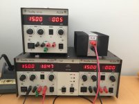
So for home, I've bought a pair of old Thurlby supplies; a dual PL320 with a gpib module in the middle, and a single PL154. They were both quite cheap and well used, so I've given them some TLC.
Date-wise there appear to be four variants:
Mine are the original. They're a bit clunky to work on because they didn't use connectors, and the display chip is no longer available, so you're stuffed if that goes, but they're very reliable.
First, the service manual is available on-line:
https://www.arklite.net/thurlby pl xxx.pdf
My left-hand supply takes a few minutes to warm up, and the voltage varies by a couple of hundred millivolts as it does which is annoying, but once warm it stays stable. Google tells me it's likely a dried out electrolytic. I swapped the obvious one (1000uf 25V for smoothing the aux supply pre-reg), but no significant change. I've ordered caps to change everything.
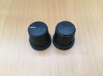
Mine was missing some of the caps from the knobs. A Cliff CL178887 is a very close match, and tops for this (Cliff CL1764) are a perfect fit.
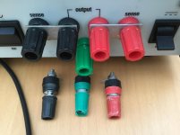
Similarly, the binding posts on mine had deteriorated. They appear to be Cliff TP2 parts (CLIFF Electronic Components - Single Terminal Binding Posts). I substituted Cliff TP1 posts which are very similar but just a tad bigger to allow for easier torquing down on wires.
Knobs, binding posts and caps are readily available from element14 (Farnell), or RS etc.
The only difficult bit to do was the shorting links. The PL supplies have a separate sense binding post for +Ve and -Ve, which is quite cool if you want to deliver exactly +5V at your PCB/battery/whatever with thin wires.
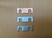
Anyway, most of the time you leave shorting links in place. These are just tin-plated copper bars that slip over the binding posts, and don't get in the way of putting wire in. Alas Mine were missing 3 of 6. I searched high and low for a source of new ones to no avail. Eventually I just hacked up some 1mm thick copper sheet to approximately the right shape and tinned it with solder.
It's good enough that my hubby can't tell which are which, so that's good enough for me.
Next on the agenda is to buy some multi-turn pots for setting voltage (50K) and current (10K), as the current ones are a little approximate, even after a good dose of contact cleaner.
Performance-wise they do what a power supply should. Output is stable within a few millivolts, and reasonably low noise. There's 50Hz harmonics, but I measure them to be suppressed to ~50uV at 16V 2A.
So the pics show the cleaned up supplies, a close up of the replacement knob (no marker line as I plan on swapping to multi-turn pots so the marker isn't that useful) next to the original knob, the process for making shorting bars (copper sheet, tinned, original), and a comparison of binding posts.
I set up a lab back in Sydney perhaps ten years ago, and bought Agilent E3642s, thinking HP, gotta be good. After the second one failed inexplicably I stole some old Thurlby supplies from a neighbouring lab and went back to them. I've never known a Thurlby supply to fail. Sure, plenty of things connected to them have lost their magic smoke, but the supplies themselves have just kept on going.
Anyway, the PL320 is a bog-basic 2A, 30V supply. The PL154 is similarly a 4A, 15V supply. Totally linear, and no switching between taps. Just an overspecced transformer, a pile of 2N3055s on some heatsinks, and a pair of reasonably nice LED displays. Newer ones went to LCD and became unreadable. They eventually went back to LEDs.
They have remote sense, and they have a DC enable switch, which is useful for setting current before you turn the load on.
So for home, I've bought a pair of old Thurlby supplies; a dual PL320 with a gpib module in the middle, and a single PL154. They were both quite cheap and well used, so I've given them some TLC.
Date-wise there appear to be four variants:
- The original two-tone brown/beige mid-'80s design, with LED displays and a rocker switch for display damping.
- An early '90s version with LED displays and a pushbutton for display damping.
- Late '90s version with LCD displays.
- Current TTi version in white plastic box.
Mine are the original. They're a bit clunky to work on because they didn't use connectors, and the display chip is no longer available, so you're stuffed if that goes, but they're very reliable.
First, the service manual is available on-line:
https://www.arklite.net/thurlby pl xxx.pdf
My left-hand supply takes a few minutes to warm up, and the voltage varies by a couple of hundred millivolts as it does which is annoying, but once warm it stays stable. Google tells me it's likely a dried out electrolytic. I swapped the obvious one (1000uf 25V for smoothing the aux supply pre-reg), but no significant change. I've ordered caps to change everything.
Mine was missing some of the caps from the knobs. A Cliff CL178887 is a very close match, and tops for this (Cliff CL1764) are a perfect fit.
Similarly, the binding posts on mine had deteriorated. They appear to be Cliff TP2 parts (CLIFF Electronic Components - Single Terminal Binding Posts). I substituted Cliff TP1 posts which are very similar but just a tad bigger to allow for easier torquing down on wires.
Knobs, binding posts and caps are readily available from element14 (Farnell), or RS etc.
The only difficult bit to do was the shorting links. The PL supplies have a separate sense binding post for +Ve and -Ve, which is quite cool if you want to deliver exactly +5V at your PCB/battery/whatever with thin wires.
Anyway, most of the time you leave shorting links in place. These are just tin-plated copper bars that slip over the binding posts, and don't get in the way of putting wire in. Alas Mine were missing 3 of 6. I searched high and low for a source of new ones to no avail. Eventually I just hacked up some 1mm thick copper sheet to approximately the right shape and tinned it with solder.
It's good enough that my hubby can't tell which are which, so that's good enough for me.
Next on the agenda is to buy some multi-turn pots for setting voltage (50K) and current (10K), as the current ones are a little approximate, even after a good dose of contact cleaner.
Performance-wise they do what a power supply should. Output is stable within a few millivolts, and reasonably low noise. There's 50Hz harmonics, but I measure them to be suppressed to ~50uV at 16V 2A.
So the pics show the cleaned up supplies, a close up of the replacement knob (no marker line as I plan on swapping to multi-turn pots so the marker isn't that useful) next to the original knob, the process for making shorting bars (copper sheet, tinned, original), and a comparison of binding posts.
Attachments
Last edited:
I'm wanting 40 V for testing amps. I had the thought of replacing the transformer and output transformers to allow higher output voltage. While it was open for measuring the transformer dimensions I checked the voltage pre-regulator. It's a whopping 56V with no load, dropping to 49V with 2.2A (max) load current. That's down to local 230V mains actually being 255V.
Given there's four 2N3055s (Vce sat <200mV) in parallel at the output, with a 1 ohm emitter resistor on each, I really only need a couple of volts headroom, so it should do 40V no problems, with no need to swap either transformer or transistors.
I changed R11 from 3K6 to 2K7, which allows me to increase the max voltage setting (RV1) beyond the standard 32V to 40V. I set it to 39.9V, as the displays run out of bits at 39.99.
All good. Going beyond 40V is much harder though, as I'd need a different display.
Last edited:
I have done the resistor trick on several lab supplies. Worst case is you run out of regulation usually. Digital displays are not too forgiving. But you may be able to find a DPM module on eBay that could work, usually for pretty cheap.
Replacing caps, transformers etc. usually gets out of hand. I have one supply here that has a fried main transformer that I gave up on. Not worth the hassle to repair.
Replacing caps, transformers etc. usually gets out of hand. I have one supply here that has a fried main transformer that I gave up on. Not worth the hassle to repair.

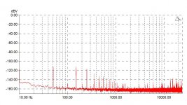
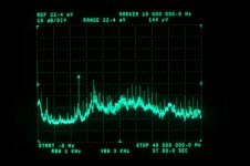
here are the ffts .. first is just PSU test cables with the terminations shorted so u get a sense of the noisy environment; then a kikusui lab-supply that's 20+ yo - and finally a chinese lab supply that just came a few weeks ago...
Oddly enough i like the old one still ...
Oddly enough i like the old one still ...
Attachments
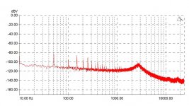
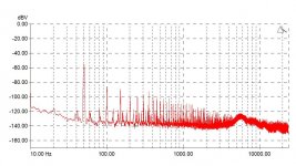
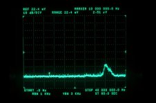
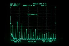
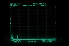
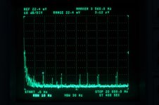
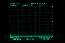
Some spectra, from DC-1KHz, DC-20KHz and DC-40MHz.
I've attached a plot of the spec-an input terminated into my 8 Ohm load with the supply switched off, then a second with the supply on set to 10V across the 8 Ohm load.
There's supply harmonics, with the worst being 150Hz, which is suppressed to 110uV pushing 1200 odd mA into 8 Ohms. Beyond 1KHz there's the odd spurious rubbish at the 3uV level.
Everything turns to custard after 10 MHz or so, with a strong 10 MHz tone at 150uV. I suspect that's coming from the GPIB control card. I imagine it'd benefit from a few strategically placed RFI split ferrites.
Anyway, it's reasonably clean, I think.
Attachments
I have several TTI PSUs, from all eras, ranging from PL320s with LED displays, through LCD-era ones, to the newer SMPS design. Fortunately, all of them work, even though one or two appear to have been in a fight with a sledgehammer. I like the ruggedness and speed of use. If I'm taking measurements, I have to use the (SMPS) 354, for exactly the reasons shown in this thread. I regularly take measurements with mains-related artefact below -120dBV on the 354. I've been wondering if the mains-related harmonics with the linear ones are due to age, or design.... The 354 needs a new mains switch.
It's funny how SMPS designs get demonised by the audio fraternity, yet the 354 is by far the most useful of our TTI supplies when examining noise. It does have some junk in the upper frequencies, but not enough to influence a 20-20 measurement.
Edit - another thing I notice is that I have to switch off any linear TTI PSUs when taking measurements, as the EI transformers throw out a fairly large field. If I'm powering something I know to be quiet, and see some junk <150Hz, the first place I look is to the right of the bench where the linear TTIs live... The junk often disappears when they are switched off, regardless of whether they are loaded (obviously, the EMI is stronger if they are loaded).
Last edited:
Finally got around to putting 5 turn pots in for coarse voltage and current. I used Bourns 3548S-1BA-103B and 3548S-1AA-503B.
Just. Wow. What an improvement. Adjustability to the display precision, and stable. Should have sprung for these years ago.
Probably worth it, but at $24 USD each, I can see why you had put it off till now.
hi all,
I have one of the brown/beige PL320 dual supplies, some general comments, partly in reply to posts by suzyj
the circuit board mounted preset pots have become erratic or even noisy with age, PR1 causes small random Voltage jumps, PR2 (going open circuit) can stop the supply working, the other presets can affect displayed readings but not the actual output Voltage or current limit,
display segment problems for me have been a faulty seg g output on one of the ADD3701 chips, a quick test is to swop over the two ADD3701 chips, if you have a faulty ADD3701 you may find it less of a problem if its placed for current display, putting a 200R pull up resistor from seg g on the ADD3701 to +Ve make my display slightly more readable!
in defence of the ADD3701 chip, the inclusion of D9 pushes the LM340T-5 output (+Ve supply) up to about 5.6V truthfully the ADD3701 spec is for a 5V supply (4.75V to 5.25V), don't know why D9 is there?
happy to look at any questions that arise,
richgwilliams
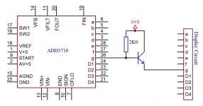
Display segment fault, Thurlby PL320 with ADD3701 display chips.
As mentioned I partially fixed a faulty ADD3701 display chip by a simple pull up resistor.
After a while I realised that the ADD3701 has a broken (open circuit) pull up fet on its segment g output. The pull down fet is working as specified. So I added the attached circuit and it fixes the missing seg g completely (for over a week so far)!
Quite a nice little chip, pity it became obsolete. The Intersil ICL7107 is still produced.
Attachments
Hi Suzy
Enjoyed reading your article about the Thurlby PL320 good job well done, I have just acquired one myself left channel LED zero volts but the current limit works, I tried getting the service manual from the link
https://www.arklite.net/thurlby pl xxx.pdf but no longer exists would you have any other links?
thanks
Andy
Web archive to the rescue:
https://web.archive.org/web/20140912140437/https://www.arklite.net/thurlby pl xxx.pdf
https://web.archive.org/web/20140912140437/https://www.arklite.net/thurlby pl xxx.pdf
Thanks SuzyWeb archive to the rescue:
https://web.archive.org/web/20140912140437/https://www.arklite.net/thurlby pl xxx.pdf
Andy, There are four functionally separate circuits in each PSU. Voltage measurement, Voltage feedback, Current measurement, Current feedback. If say Voltage measurement fails then Voltage feedback may still be working, Knowing this helps to fault find.
The Voltage and Current circuits are very similar but not the same eg the current measurement chip is not grounded, rather it sits above ground by a diode drop.
Replacing the Coarse Voltage pot with a multturn pot is a good idea (as per Suzy's posts). I use my Thurlby to test charge Lithium batteries so a stable 4.2 Volts etc is needed.
A good way to test for output noise is connect the output to an 8 Ohm speaker, put less than an Amp into the speaker, try in CV and CC, my Thurlby gives some high pitch tone and a little pot noise, which is OK.
Be careful about increasing the output Voltage (as mentioned by Suzy), above 30 Volts is problematic. Also worth noting that a circuit fault or output transistor fault can put the full rectified transformer voltage (and current) onto the output (about 50 to 55 Volts) and there is no secondary circuit or crowbar to protect against this.
I replaced the output transistors with Mosfet but that's another story and it wasn't easy 😂
A fine old faithful PSU.
Rich
- Home
- Design & Build
- Equipment & Tools
- Elderly Thurlby PL320 & PL154 lab supply tidy-up.