That's how it is supposed to be- I can't read anything...

No, too much potentially valuable IP about which I am still undecided....Too much compression?
In their July/August edition of 2016, Elektor published an AD8479 based current probe for oscilloscopes with differential inputs, designed for 'floating' measurements without any reference to ground. Perhaps this might be the one you're looking for?
Oops, just saw that this might apply to the German edition exclusively...
Best regards!
Oops, just saw that this might apply to the German edition exclusively...
Best regards!
A probe that has a large common-mode handling capability, wide bandwidth, high differential sensitivity and low noise is the holy grail of differential measurements...
The holy gral - hmmm? And the active common mode killer is Sir Lancelot? I like the idea
Maybe thinking over what exactly should be measured will reduce the requirements to less holy levels. In the class-d case, for example, the higest bandwidh is needed to see overshots and ringing in the moment of switching. A classical (not differential) probe is completly sufficient for this.
> THAT's ingenius stuff simiplfies all of this
An excellent chip for line receiver work.
Input impedance is 48K. High for many purposes, low for some internal probing.
Since it includes all the precision trim, you could drop a pair of unity-gain TL072/? in front to get infinite Z with large CMRR.
An excellent chip for line receiver work.
Input impedance is 48K. High for many purposes, low for some internal probing.
Since it includes all the precision trim, you could drop a pair of unity-gain TL072/? in front to get infinite Z with large CMRR.
Attachments
There are the high-votage differential probes, the high-frequency
diff-probes and the low-level signal differential probes.
The requirements for these are contrary, therefore don't mix them up.
Last year i have bought the 50 MHz Pintek DP-50 probe.
The price was about 330 €. The probe does what i expected.
The housing is of very good quality, a bit too big maybe.
The circuit is in principe the 3-opamp differential amplifier.
The big dissapointment is the input protection:
The creapage and clearance distances are no more than about 2x 3 mm
(or even less - can't remember now)
That makes it only a 300 Volt CAT-III probe (See IEC 61010).
Be aware that this information is not stated anywhere! The label 6.5 kVolt
CAT-III on the housing have criminal tendencies!
And i don't trust the tiny and brittle input capacitors and resistor network.
This capacitors are prone to cracks due to mechanical stress.
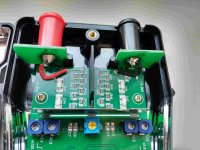
The PCB is not very clean, and the big switch in the middle makes it
necessary to route the high-frequency signals
forward and backward half the print.
Otherwise the print is of good quality.
The handbook looks good, but is crap too.
Important information like the input impedance is clearly wrong
(8 MOhm measured).
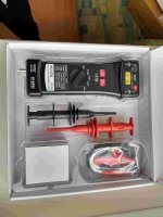
The supplied leads and grippers are of good quality.
The BNC cable is even isolated, so that you have
additional safety in case that the input divider is faulty.
This thread has a circuit of the 25 MHz DP-25:
http://www.diyaudio.com/forums/equipment-tools/248505-differential-probe-reverese-engineered.html
A lot of information can be found on the eevblog.com site:
https://www.eevblog.com/2016/10/11/eevblog-932-how-does-a-hv-differential-probe-work/
High Voltage 10-100MHz Differential Probe Investigated - Page 1
Tektronix P5200 Differential Probe Teardown - Page 1
diff-probes and the low-level signal differential probes.
The requirements for these are contrary, therefore don't mix them up.
Last year i have bought the 50 MHz Pintek DP-50 probe.
The price was about 330 €. The probe does what i expected.
The housing is of very good quality, a bit too big maybe.
The circuit is in principe the 3-opamp differential amplifier.
The big dissapointment is the input protection:
The creapage and clearance distances are no more than about 2x 3 mm
(or even less - can't remember now)
That makes it only a 300 Volt CAT-III probe (See IEC 61010).
Be aware that this information is not stated anywhere! The label 6.5 kVolt
CAT-III on the housing have criminal tendencies!
And i don't trust the tiny and brittle input capacitors and resistor network.
This capacitors are prone to cracks due to mechanical stress.
The PCB is not very clean, and the big switch in the middle makes it
necessary to route the high-frequency signals
forward and backward half the print.
Otherwise the print is of good quality.
The handbook looks good, but is crap too.
Important information like the input impedance is clearly wrong
(8 MOhm measured).
The supplied leads and grippers are of good quality.
The BNC cable is even isolated, so that you have
additional safety in case that the input divider is faulty.
This thread has a circuit of the 25 MHz DP-25:
http://www.diyaudio.com/forums/equipment-tools/248505-differential-probe-reverese-engineered.html
A lot of information can be found on the eevblog.com site:
https://www.eevblog.com/2016/10/11/eevblog-932-how-does-a-hv-differential-probe-work/
High Voltage 10-100MHz Differential Probe Investigated - Page 1
Tektronix P5200 Differential Probe Teardown - Page 1
Attachments
I would look at exploiting the CM feedback with external opamps to reduce any common mode, especially if you need gain from them. I would use something like an OPA2134 for FET input opamps for lower noise and better linearity.
This approach is problematic because it does not work well with high voltage or high speed input
transients and it lowers the effective common mode
impedance. In most cases you want a very high CM impedance.
In addition the common mode rejection is always limited by the input resistor tolerances and not by the active diff-amplifier.
So no need to use fancy circuits.
A bit late for the fun.
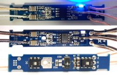
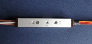
We needed one and we made one, for audio use.
Essentially a single AD8421 with a pair of 1M ohm attenuators upstream.
(You can choose your ratio to suit application. I used 9:1.)
Switchable AC / DC coupling, switchable differential gain 1x/10x.
Option to limit bandwidth with a shunt cap (NP0).
With 0.1% Susumu 0805 resistors, we achieved better than -75dB CMRR from 100Hz to 50kHz on our test board.
Expect that to improve further when properly housed and shielded with battery supplies.
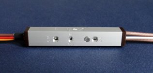
PCB is 54mm x 8mm. Will fit into an aluminium tube of 10x10x60mm. PSU external.
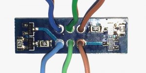
PCB layout is fully symmetrical for both inputs.
Signal cables in (2x) and out will be RG179.
Quite happy with the results.
Really good chip, especially the high input impedance.
Patrick
PS the picture posted here is a low voltage version with no attenuation (1:1000).
.
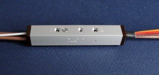
We needed one and we made one, for audio use.
Essentially a single AD8421 with a pair of 1M ohm attenuators upstream.
(You can choose your ratio to suit application. I used 9:1.)
Switchable AC / DC coupling, switchable differential gain 1x/10x.
Option to limit bandwidth with a shunt cap (NP0).
With 0.1% Susumu 0805 resistors, we achieved better than -75dB CMRR from 100Hz to 50kHz on our test board.
Expect that to improve further when properly housed and shielded with battery supplies.
PCB is 54mm x 8mm. Will fit into an aluminium tube of 10x10x60mm. PSU external.
PCB layout is fully symmetrical for both inputs.
Signal cables in (2x) and out will be RG179.
Quite happy with the results.
Really good chip, especially the high input impedance.
Patrick
PS the picture posted here is a low voltage version with no attenuation (1:1000).
.
Attachments
To much work to make product, especially the machining.
We can send you PCBs. How many do you want ?
You can make your own housing if we publish drawings ?
If not we need to see when we can do ourselves.
Currently CNC facility is not operational.
Will take a few months, unfortunately.
Cheers,
Patrick
We can send you PCBs. How many do you want ?
You can make your own housing if we publish drawings ?
If not we need to see when we can do ourselves.
Currently CNC facility is not operational.
Will take a few months, unfortunately.
Cheers,
Patrick
For reference (not the same circuit as we used) :
https://www.circuitsonline.net/forum/view/118515
Google translate will give you a very good idea.
Patrick
https://www.circuitsonline.net/forum/view/118515
Google translate will give you a very good idea.
Patrick
We are famous for taking ages.
The electronics was easy, but the mechanical stuff takes a while.
Very pleased with the results though.
Patrick
.
The electronics was easy, but the mechanical stuff takes a while.
Very pleased with the results though.
Patrick
.
Attachments
Last edited:
The electronics was easy, but the mechanical stuff takes a while.
Very pleased with the results though.
Looks nice, now fit a 7A22 in that box.
Nice work, Patrick (as always)!
Me, I got lucky and bought a Tek 5223 from Medtronic's laboratories (the company which makes heart pacemakers) -- came with a 5A22N.
Manual for 7A22N can be found here: http://bama.edebris.com/manuals/tek/7a22/
Me, I got lucky and bought a Tek 5223 from Medtronic's laboratories (the company which makes heart pacemakers) -- came with a 5A22N.
Manual for 7A22N can be found here: http://bama.edebris.com/manuals/tek/7a22/
- Status
- This old topic is closed. If you want to reopen this topic, contact a moderator using the "Report Post" button.
- Home
- Design & Build
- Equipment & Tools
- DIY Balanced / Differential oscilloscope probes?