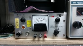
I have an old tube based Kepco ABC 425M that died. The power tube is a 8068 beam power tube. Before I order a new tube I want someones opinion on whether to replace it or not.
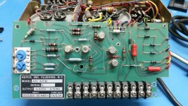
I was messing with another high voltage source and the Kepco wires were connected by mistake/stupidity. I heard a zap the quickly powered everything down. The Kepco was the only piece that didn't survive. When I power it up the voltage is at zero for a few seconds. As the tube filament heats the voltage on the panel meter raises to a full 500 voltage regardless of where the front adjustments are. I've opened the unit and can find no burn marks on any parts. I've removed all the transistors from the PCB. Using my DMM I've done basic testing and they seem fine. (Basic NPN PNP transister tests.) There are also a hand full of diodes on the back. I removed one side from each and did basic diode tests and all seem fine. I've also tested the power tube but I only have a Mighty Mite VII tube tester. It tests fine but i'm guessing the tube could have been damaged in a subtle way that the tester might not show. Anyway I'm about to order a replacement but would like any advise from the experts.
Thanks,
Tevian
Attachments
The pass tube is the least likely component in the whole unit to be damaged this way.
Do you have the schematics?
Depending on the voltage setting feedback scheme it is possible that the voltage setting pot is now open. I have seen that occur in other non Kepco supplies. I would suspect any components on the output side that are involved with setting the output voltage.
It is not impossible for the tube to be damaged, but your description of the problem makes it sound like the tube might be OK.
The 8068 may at times be difficult to source, but if you can get one having a spare is not a bad idea.
Wow! Good call!
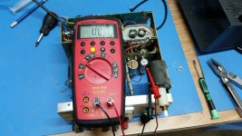
The voltage adjustment pot is open circuit. The current pot looks good. I couldn't find the schematic for this thing. Now I have to find a replacement for the pot. I've never purchased an 8068 but NOS tubes are in the $20-30 range on ebay so not too bad.
") Thanks!
Thanks!
The voltage adjustment pot is open circuit. The current pot looks good. I couldn't find the schematic for this thing. Now I have to find a replacement for the pot. I've never purchased an 8068 but NOS tubes are in the $20-30 range on ebay so not too bad.
Thanks!Attachments
Ouch! These pots look expensive! Do these look right?
(link to Digikey large 500k multiturn pots)
Rotary Potentiometers, Rheostats | DigiKey
How close to 425k ohm should I be?
(link to Digikey large 500k multiturn pots)
Rotary Potentiometers, Rheostats | DigiKey
How close to 425k ohm should I be?
The 500K pot should work fine, but might result in an excessively high voltage setting at the extreme top end of the voltage setting range. You could try shunting it with approximately 3.0M of resistance, (I recommend 3 x 1M 1% 0.5W in series) and that would would put you fairly close.) you can try end to end or wiper to low V end and see what works best or if it matters at all.
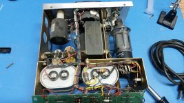
Something else to note is how much voltage the pot can tolerate across it. Look at the trouble they have gone to in order to isolate the shaft from the panel, you may have to cobble something up to provide isolation so that an internal insulation breakdown does not occur.
Edit: The TTI component can apparently withstand 1kV so 500V should be OK and it is likely OK to mount directly to the panel, if you can figure out how to isolate it that still might be better.
Edit: The TTI component can apparently withstand 1kV so 500V should be OK and it is likely OK to mount directly to the panel, if you can figure out how to isolate it that still might be better.
> a 8068 beam power tube
Basically a 6L6 frame, 6L6GC plate ratings, with top-cap. Even the perveance is about what you expect for a 6L6 working at just 125V on G2 (on 8068 pentode data; the regulator may be using it Triode). If the out-of-control voltage is 500V, any new-made "6L6" should drop-in with socket/cap re-wiring.
Basically a 6L6 frame, 6L6GC plate ratings, with top-cap. Even the perveance is about what you expect for a 6L6 working at just 125V on G2 (on 8068 pentode data; the regulator may be using it Triode). If the out-of-control voltage is 500V, any new-made "6L6" should drop-in with socket/cap re-wiring.
The 10 turn pot is a critical part of the system. Its unusual for those to be open. Is it open between the wiper and both ends? The 425K value is important for the max setting. Shunting with a resistor will screw up the pot readings. The supply drops a known current across the resistance of the pot to set the voltage. Higher resistance mean higher voltage. All the way up at 500K would raise the output probably to an unregulated level. Otherwise not an issue.
Look at eBay for something like that. This is the closest I found: 300K ohm 10 turn wire big potentiometer LITTION SERVOTECHNIK W. Germany 1 pcs | eBay You would need to figure out how to increse the current enough. There are also 250K 10 turn pots. Many others but you can sift through yourself.
Look at eBay for something like that. This is the closest I found: 300K ohm 10 turn wire big potentiometer LITTION SERVOTECHNIK W. Germany 1 pcs | eBay You would need to figure out how to increse the current enough. There are also 250K 10 turn pots. Many others but you can sift through yourself.
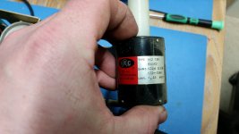
Just a quick response. It's hard to see but the two outside pins are connected with a wire. So one end and the wiper are joined. So there are only two wires connecting the pot to the pcb. I'm sorry if that's obvious. Anyway, I'll search around for something close and post again later.
Thanks.
Thanks.
- Status
- This old topic is closed. If you want to reopen this topic, contact a moderator using the "Report Post" button.
- Home
- Design & Build
- Equipment & Tools
- Kepco ABC 425M power supply dead. :(