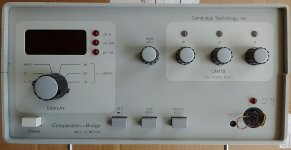
I was given one of these meters a few years ago without a probe cable or any manuals. The probe plug is a 5 pin DIN connector and I'm not sure of the pin out. Opened it and found one of the voltage regs burning up, turned out the orange tantalum cap on the output was shorted - fixed it. I get a reading of 5 ish pF even when putting a bigger cap between pins on the DIN connector. I found the ground, and a pin with DC bias when enabled, but when I put a cap across the other pins I don't get a reading. It is from 1988 and looks to be in perfect condition.
Anyone familiar with this thing or have a manual?
Thanks!
Edit: I got it working, more or less. Facing the 5 pin connector, as you would to plug in a cable: center bottom pin is ground Left bottom is osc out, that has DC bias on it when enabled. Left top seems to be an input and has to be jumpered to osc out, probably osc sense. Device under test goes to osc out, and to right upper. Right upper is DUT input, it seems. Not sure what right lower is, seems to be an input but so far not needed.
Measuring a cheap mylar 4.0 uF cap is 3.95 dead on agreement with my Fluke meter. Measuring two 1mH inductors gave 998 uH and 1005 uH seems that it is working. All the trimmer have paint on the screws that doesn't look cracked, I don't think anyone else has been inside the unit.
It would still be nice to have some documentation and alignment procedure.
Last edited:
From your description, plus its typical of that type of instrument, it has full Kelvin sensing. it needs both source and sense connections which is why there is an input on the low side. You need to make a full Kelvin probe assembly to get use. Fortunately they are cheap in China now. This may even be wired right for your instrument Kelvin Clip to DIN 5-pin for LCR test probe #999-001 (USA) | eBay . At least its a great start. I remember when the clips were $100 ea.
Does anyone have the manual for this meter, there are a few controls
that I can't figure out?
Most of them are obvious:

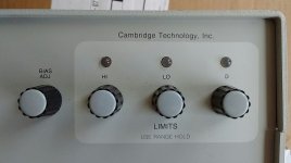
But it is not clear what these are for, they are all 10 turn pots:
I'm not sure what the hi/lo range limits are for and it just hit me that you turn the meter switch in order to set the value on the display. It says "range hold" under the pots, and I assume that you press the button along the bottom perhaps to set them?

that I can't figure out?
Most of them are obvious:

But it is not clear what these are for, they are all 10 turn pots:
I'm not sure what the hi/lo range limits are for and it just hit me that you turn the meter switch in order to set the value on the display. It says "range hold" under the pots, and I assume that you press the button along the bottom perhaps to set them?

Last edited:
Say you are testing cheap 220pFd caps to 1% tolerance.
First cap, you hit Range Hold so it stays in the hundreds-pFd range, does not auto-range for every new part presented.
You set HI to 222 and LO to 218. Then you can hire illiterate operators and they only have to read the lights, not the numbers. If a part is HI or LO they set it aside for slop-work. If a part is neither HI nor LO they put it in the 1% bucket as a "Selected Part". (This mode may have to use Range Hold so it knows it is looking for a narrow range of values.) Obviously this is for BIG production with CHEAP operators, not smart DIY folks who love actual numbers and don't have a ton of parts to check.
Sounds like the sort of task one of these New Caledonian crows could master!Say you are testing cheap 220pFd caps to 1% tolerance.
First cap, you hit Range Hold so it stays in the hundreds-pFd range, does not auto-range for every new part presented.
You set HI to 222 and LO to 218. Then you can hire illiterate operators and they only have to read the lights, not the numbers. If a part is HI or LO they set it aside for slop-work. If a part is neither HI nor LO they put it in the 1% bucket as a "Selected Part".
Crow vending machine skills 'redefine intelligence' - BBC News
Bought the lead set from ebay and also a matching panel jack.
Removed the original PC mount jack and installed the new one with short
wires running down to the board.
Powered it up and the display read 1 and did nothing. Felt the voltage reg
heat sinks and again one was burning up. The orange drop Tantalum cap (2.2uF 25V)
on the complementary +/-15V supply shorted. Replaced it and back working but it
is very intermittent. It often powers up reading 998 with no response to input.
Found that slight flex to the PC board made it work again, tried to reflow many
solder joints with no success. It was very sensitive to tapping near the input jack
and it hit me that the old jack being PC solder mount stressed that corner of the
board. Reflowed most of the connections in that corner and now it seems to be
reliable.
Thanks everyone for all the help!
- Status
- This old topic is closed. If you want to reopen this topic, contact a moderator using the "Report Post" button.
- Home
- Design & Build
- Equipment & Tools
- Cambridge Technology Inc 520 L/C Meter?