Hello Suzyj,
Nice build !")
As you have experienced, the THD of the oscillator is extremely low and so not so easy to measure..
I use a high depth TwinT filter followed by 40dB post gain to made my measurement.
Of course all in shielded box and well verified to avoid introducing any THD from the gain block.
FRex
Nice build !
As you have experienced, the THD of the oscillator is extremely low and so not so easy to measure..
I use a high depth TwinT filter followed by 40dB post gain to made my measurement.
Of course all in shielded box and well verified to avoid introducing any THD from the gain block.
FRex
my oscillators 1kHz and 10kHz
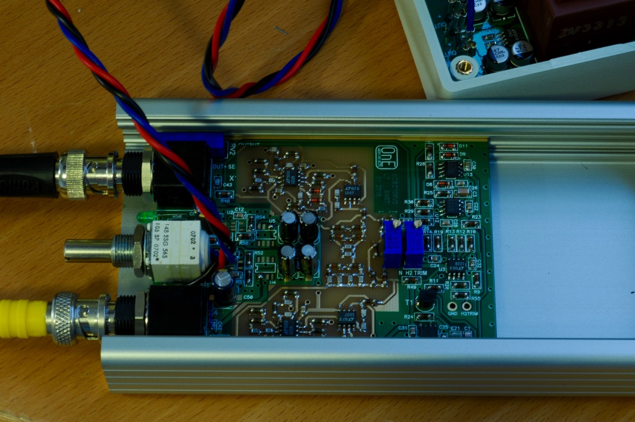
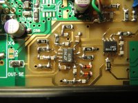
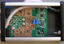
I have fixed my oscillators 1kHz and 10kHz.Power is eneloop x24.Voltage is from 17V (after full charge) to 13V.There is no battery protection because NIMH is not dangerous in over-discharge. When the oscillation stops, it's time to charge. 20 hours operation is probably possible. Registers are thin film 0805 or 1206.
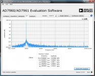
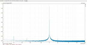
I measured THD using the AD7960 Eva board. AD7960 is 5Msample SAR ADC.I want to use this for my new ADC for measurement purpose. Performance is very good as described in the data sheet. The noise level is almost same (approx. -117dBFS at 20kHz bandwidth) regardless of input level contrary to most delta sigma.
THD is almost -120dBFS both 1kHz and 10kHz.I think this is reliable because another ADC Eva board (AD7768) also indicated the similar value.But -120dBFS is very small. It doesn't mean absolute one, but reference, IMHO.
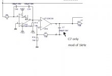
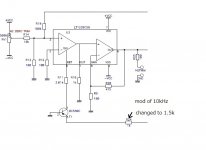
I need to some mod for better operation. I changed the value of R24 from 1k to 1.5k in 10kHz oscillator. The voltage of collector of a T1 is almost above zero without modification. This result in unstable startup. After the mod, the voltage is below zero and it begins to start constantly. I don't know the reason why. It ends up a stable oscillation now.
1kHz had another problem though collector of a T1 is -3v with 1k resistor. It oscillates at not 1kHz but almost 3MHz unexpected frequency. I think there are many cases of like this high frequency oscillation. It takes half a day to fix. I don't much experience about an analogue oscillator.
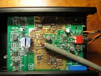
What you need to do in this analogue situation is almost same as long as I know. The best tool is a finger.Touching around ICs and other components to find out the unexpected high temperature. This is of course for semiconductor PCB not applicable to tubes. High temperature teaches you unexpected operation like unusual oscillation. Scope is the 2nd tool to analyze precisely.
After finger checks, I found U9 is not a normal operation compared with another OP amp. I don't know the exact operation theory of the circuit. I guess elimination of high frequency like 3MHz is not done correctly. When I happened to forget to connect R17 to gnd during trial and error, unusual high oscillation stopped and only 1kHz oscillated.
I finally removed C8, R17, D16 and D17.I think this is not common for the circuit, but only for my 1kHz oscillator. But this can be some tip for those who unluckily encounter unusual oscillation trouble. An analogue oscillator at low cost with less than -120dbFS THD is surprising. This is a good tool for DIY. Thank you Frex.
I have fixed my oscillators 1kHz and 10kHz.Power is eneloop x24.Voltage is from 17V (after full charge) to 13V.There is no battery protection because NIMH is not dangerous in over-discharge. When the oscillation stops, it's time to charge. 20 hours operation is probably possible. Registers are thin film 0805 or 1206.
I measured THD using the AD7960 Eva board. AD7960 is 5Msample SAR ADC.I want to use this for my new ADC for measurement purpose. Performance is very good as described in the data sheet. The noise level is almost same (approx. -117dBFS at 20kHz bandwidth) regardless of input level contrary to most delta sigma.
THD is almost -120dBFS both 1kHz and 10kHz.I think this is reliable because another ADC Eva board (AD7768) also indicated the similar value.But -120dBFS is very small. It doesn't mean absolute one, but reference, IMHO.
I need to some mod for better operation. I changed the value of R24 from 1k to 1.5k in 10kHz oscillator. The voltage of collector of a T1 is almost above zero without modification. This result in unstable startup. After the mod, the voltage is below zero and it begins to start constantly. I don't know the reason why. It ends up a stable oscillation now.
1kHz had another problem though collector of a T1 is -3v with 1k resistor. It oscillates at not 1kHz but almost 3MHz unexpected frequency.
I think there are many cases of like this high frequency oscillation. It takes half a day to fix. I don't much experience about an analogue oscillator.What you need to do in this analogue situation is almost same as long as I know. The best tool is a finger.
Touching around ICs and other components to find out the unexpected high temperature. This is of course for semiconductor PCB not applicable to tubes. High temperature teaches you unexpected operation like unusual oscillation. Scope is the 2nd tool to analyze precisely.After finger checks, I found U9 is not a normal operation compared with another OP amp. I don't know the exact operation theory of the circuit. I guess elimination of high frequency like 3MHz is not done correctly. When I happened to forget to connect R17 to gnd during trial and error, unusual high oscillation stopped and only 1kHz oscillated.
I finally removed C8, R17, D16 and D17.I think this is not common for the circuit, but only for my 1kHz oscillator. But this can be some tip for those who unluckily encounter unusual oscillation trouble. An analogue oscillator at low cost with less than -120dbFS THD is surprising. This is a good tool for DIY. Thank you Frex.
Attachments

Hello xx3stksm,
You have done a good job.
Note that you can encounter wrong behavior of the oscillator (HF oscillations...) if there is any soldering flux trace on the PCB.
It is strongly recommended to clean the PCB with isopropylic alcohol.
In fact, the OPAMP's used (LT1229) are current feedback type and then are very sensitive to parasitic capacitance.
Note also that some capacitors are critical and must be good quality (NPO/COG) for best performance.
So now, you are ready for measurements !
Best regards.
Frex
You have done a good job
.Note that you can encounter wrong behavior of the oscillator (HF oscillations...) if there is any soldering flux trace on the PCB.
It is strongly recommended to clean the PCB with isopropylic alcohol.
In fact, the OPAMP's used (LT1229) are current feedback type and then are very sensitive to parasitic capacitance.
Note also that some capacitors are critical and must be good quality (NPO/COG) for best performance.
So now, you are ready for measurements !
Best regards.
Frex
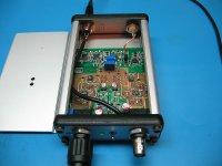
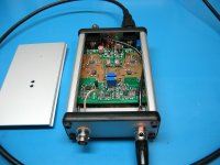
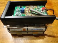
Just, I done two of these marvelous oscillators, one for 1K and the other for 10K.
I sprayed a nickel inside the hammond cases for better isolation from outside EMI.
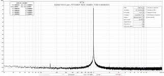
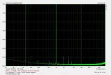
With 1K and differential connection with my RTX6001 Audio Analyser, I achieved a THD 0.000024% - 0.000026% without notch filter.
Thanks Frex.
I sprayed a nickel inside the hammond cases for better isolation from outside EMI.
With 1K and differential connection with my RTX6001 Audio Analyser, I achieved a THD 0.000024% - 0.000026% without notch filter.
Thanks Frex.
Attachments
That's exceptional performance. However you need to be careful about drift. I have been burned before when the oscillator drifted enough that the harmonics weren't in the same bin for subsequent measurements.
Let the system stabilize for some time (usually 10 minutes at least). If you can monitor the frequency with high accuracy it helps.
I would use DiAna Home DiAna, a software Distortion Analyzer for this measurement. It seems to track well when set to external reference.
Those results are really better than I have seen with almost any source or analyzer. If they are reproducible I'll need to build more hardware.
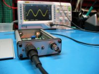
The frequency is very stable, with my Fluke45 I have seen frequencies from 1.0018-1.0019 not out of these at this amplitude level.
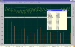
The results are reproducible, a new capture (today) with a little 50Hz hum (my PSU is open on a wood plate) is indicated 0.000026%
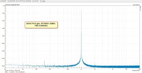
With Dianna 1.48.9 and no calibration on relative menu, just to see the almost level as before, the THD is extraordinary.
The results are reproducible, a new capture (today) with a little 50Hz hum (my PSU is open on a wood plate) is indicated 0.000026%
With Dianna 1.48.9 and no calibration on relative menu, just to see the almost level as before, the THD is extraordinary.
Attachments
Hello,
From the beginning i always have a little bare PCB in stock because of some demand.
So i order small batch to satisfy DIYers (PCBcard that make very good job).
Unfortunatly Demian, i don't have much time and so i only provide bare PCB.
Note that i provide the paste file to simplify SMD soldering for those use an oven.
There is also the very complete design folder included (zipped folder),
and a sticker for for rear and front panel.
The PCB price is unchanged : 17€ including shipping inside EU and 18€ outside.
Best regards.
Frex
I am putting together a BOM on DigiKey for this. Given the current scarcity of MELFs, I am planning on using Panasonic's ERA8A which are 1206 SMT, ±0.1%/±25ppm/0.25W and DigiKey has a very wide range of values in stock: ERA-8A Series - Panasonic Electronic Components - Thin Film | Online Catalog | DigiKey Electronics.
One component I can not find were the specified LL4148 diodes. The BOM states "Vrrm 100V, Ifav 150mA", however I am looking to use PMLL4148L,135 Nexperia USA Inc. | Discrete Semiconductor Products | DigiKey. These have 75V max DC reverse and 200ma Current - Average Rectified. Vf is the same 1V @ 50mA. Is this a good replacement?
One component I can not find were the specified LL4148 diodes. The BOM states "Vrrm 100V, Ifav 150mA", however I am looking to use PMLL4148L,135 Nexperia USA Inc. | Discrete Semiconductor Products | DigiKey. These have 75V max DC reverse and 200ma Current - Average Rectified. Vf is the same 1V @ 50mA. Is this a good replacement?
My question is a bit off-topic, but I'm seeing familiar names...
What do you guys do you recommend as a sound card for FFT spectrum measurements? I'm thinking a USB external device would be good for avoiding computer chassis noise and would allow use of a USB isolater to prevent ground loop issues. But it's a big universe.
Thanks for your advice.
What do you guys do you recommend as a sound card for FFT spectrum measurements? I'm thinking a USB external device would be good for avoiding computer chassis noise and would allow use of a USB isolater to prevent ground loop issues. But it's a big universe.
Thanks for your advice.
Interesting: Audio Precision is using a pure sine gen too. YouTube video at 2:20. THD+N goes from -108dB to -115dB. But the have "additional signal processing, notch filters and ADCs" that lead to -121dB.
Some tricky from AP!
The first that I saw is that the AP presents THD+N and not THD without noise.
The DAC as signal generator goes to -108dB THD+N and with some tricky on processing and notch filter with the special high performance AP generator goes to -121dB that is the best of the market.
Is that true?
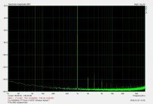
Here is a capture from RTX6001 Audio Analyzer, a loopback test with the same amplitude signal as AP and some tricky on generator DAC part.
Almost the same THD+N (-120.3/-120.9dB) with the giant AP, without a special generator and without a notch filter!
Attachments
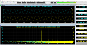
Here is the RTX with loopback cables in place. You are seeing the actual output and input residuals. To be clear, this is not a software loopback, it is the real performance of the RTX. This is an early test before I got MI, so I'm using ARTA.
I am more than happy with this hardware.
-Chris
I am more than happy with this hardware.
-Chris
Attachments
- Home
- Design & Build
- Equipment & Tools
- EOSC10Kv3 - LT AN67 10kHz oscillator : new updated version !