I don't understand all the details involved in this. How much drift should we expect, say during one minute or one hour? 1%? 10%? 100%? Just a rough estimate would be useful to understand if this is worth pursuing, and how often a calibration (in the software) would be required to attain a certain level of accuracy.
Jens: Let's assume I want to find out how this works simply by trying it (and voiding the warranty by doing this). Will grounding the DAC HPFE pin to GND upset the functioning of the electronics in any way? Will it cause a short, burn a part, or similar problem? I don't have a schematic of the involved circuitry, so I am "blind".
Grounding the HPFE pin will not "upset" the functioning.
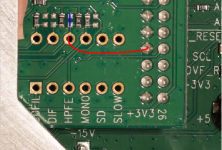
If you insist, this is the way you can disable the high-pass filter. Either mount a 0 ohm resistor along the blue line in the picture or mount a piece of wire along the red line.
This is not an authorized mod, and any unauthorized mod will void the warranty.
I don't intend to characterize the DC performance.
Attachments
Hi mbrennwa,
The proper instrument for the proper job. Trying to show drifting mV offset against the signal, noise and other signals (harmonics, etc.), the DC drift would be lost just due to the scales involved. Again, the RTX isn't the proper instrument for this kind of work.
I guess you could make a DC front end for the RTX where you chop the filtered input signal and look at the magnitude of that signal at the first harmonic (the rest being the chopping energy). I have never tried this, but you essentially shift the DC into something within the normal passband of the RTX or whatever spectrum analyser you wish to use. Software could probably convert that back onto a DC display for you and you could get your trend data that way. I'd still just use my meter.
Best, Chris
Same here. I use my oscilloscope, or another THD analyser (HP 339A) and look at the residuals with a 'scope and / or a spectrum analyser. I have an analogue spectrum analyser too ( HP 3585A) for when I'm chasing problems. Happily the RTX has enough resolution to find issues so that my other spec-ans aren't needed for this work.But who says I want frequency vs. amplitude always? There are so many ways of looking at measurement data (time domain, frequency domain, whatever).
For that situation I always use my bench meter (HP 34401A) that allows me to look at trends also in addition to peak +/- and average DC. These measurements are filtered to exclude the signal which when looking at DC drifts, is just noise. I can do the same with my 'scope (Agilent 54642D), but without the resolution the meter affords.If there's DC in the signal, sure, that's what it should be.
The proper instrument for the proper job. Trying to show drifting mV offset against the signal, noise and other signals (harmonics, etc.), the DC drift would be lost just due to the scales involved. Again, the RTX isn't the proper instrument for this kind of work.
Yes, yes and maybe not. The RTX is inexpensive enough against the really high end meters. It's just not the right instrument for that job really.Better in what way? Better accuracy and precision? Ergonmics? Cost?
The biggest problem you would run into is that the RTX wouldn't range properly in the presence of higher frequency signals. You would always be working with very low ENOB and very low precision as a result. A simple <good> meter will always outperform the RTX or any spectrum analyser in this situation. Again, the proper instrument for the job at hand. The one situation I could see is if you wanted to dynamically study DC conditions during an amplifier failure. That might be an interesting study for speaker manufacturers. But for normal audio applications, the industry does everything possible to avoid DC and the processing of same. It is not relevant to the operation of audio equipment unless DC offset exists. THen it represents a failure in design or operation of the equipment.I don't have any particular application in mind, but getting the full data into the software from a single instrument (the RTX) would be convenient and transparent.
Unfortunately the DC bin has artifacts from the process of FFT, making that bin invalid. You see this in > $30,000 instruments, it is always there and you can't get rid of it. So the DC bin never has anything in it worth looking at due to the very process of FFT.That's exactly what the FFT does for the DC bin.
Well, we are in perfect agreement on that then.Yes, sure. I do this kind of averaging with sensor and mass spec data all the time in my real job. But it only works if the instrument does not throw away the DC part of the signal. I guess what you wrote is exactly what I was trying to say all the time.
I guess you could make a DC front end for the RTX where you chop the filtered input signal and look at the magnitude of that signal at the first harmonic (the rest being the chopping energy). I have never tried this, but you essentially shift the DC into something within the normal passband of the RTX or whatever spectrum analyser you wish to use. Software could probably convert that back onto a DC display for you and you could get your trend data that way. I'd still just use my meter.
Best, Chris
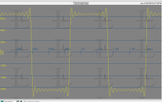
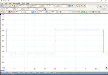
To get rid of the controversial topic "DC offset", here an example without DC offset where you see an effect of the low pass filter: A 96Hz square wave. The amplitude even visibly drops slightly inside a square, instead of being constant.

I used as source the Soekris DAM, if it does one thing next to perfect its square waves, when all filters are bypassed. This avoids additional effects of the filters on the DAC side.
Moreover there is a funny oscillation in the overshot, but I thing this is due to slightly different clock rates and therefore in the amount of hitting the quite sharp overshot.
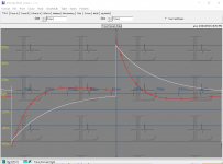
The ringing is I believe called Gibbs Phenomenon. Attached are three pictures of a square wave from a very fast rise function generator (Krohn Hite 2200). First is a 200 MHz Picoscope. The actual measured rise time is 6.5 nS, no ringing. Second is the ADC of the RTX6001 at 192 KHz. Third is the ADC at 48 KHz.
What you are seeing is the effect of the anti-alias filters. Then a 1Hz square wave through the DC coupled scope. Finally the same 1 Hz into the RTX with DC (white) and AC (red) coupling.
Nothing here unexpected.
Personally I find there are few situations where a scope is the right tool for DC measurements.
Attachments
First I did a "typo", I meant you see a effect of the high pass filter without DC offset - the drop of the amplitude of the rectangle.
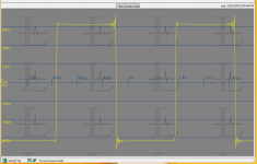
To the overshot: I do not claim the overshot itself a problem, I know it is the normal effect of the bandwidth limitation of the ADC. I only mentioned it as there is the funny effect that there is an oscillation in the magnitude of the overshot of successive rectangles (second picture on my previous post) or even more zoomed out here.

In my tentative explanation I used again a wrong word. I thing it might be explained in the different amount captured from the rising/falling flank of the rectangular wave due to clock differences of the DAC and ADC.
To the overshot: I do not claim the overshot itself a problem, I know it is the normal effect of the bandwidth limitation of the ADC. I only mentioned it as there is the funny effect that there is an oscillation in the magnitude of the overshot of successive rectangles (second picture on my previous post) or even more zoomed out here.
In my tentative explanation I used again a wrong word. I thing it might be explained in the different amount captured from the rising/falling flank of the rectangular wave due to clock differences of the DAC and ADC.
The oscillation is due to aliasing caused by the (low) resolution on the screen compared to the resolution of the measurement.
No. If you zoom in (or look at the numerical data) and compare you see it is reel.
Are you sure that all samples are present when you zoom in?
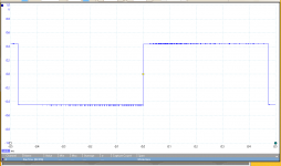
Yes, you can zoom in at sample level, here two extreme examples:


Notice the location of the samples next to zero crossing - therefor I think the effect is due to how much of the quite sharp flank is caught.
Jens, can the SE analogue output (set to 10Vrms) drives right a stepped ladder attenuator with Zin 600R?
If that is limited what Zin is good for this output?
I have in my mind the project AT2380v1 // 2 Channels digitally controlled stepped attenuator as an attenuator on SE RTX output to measure final amps.
If that is limited what Zin is good for this output?
I have in my mind the project AT2380v1 // 2 Channels digitally controlled stepped attenuator as an attenuator on SE RTX output to measure final amps.
The single ended output delivers a maximum of 5 Vrms. The output impedance is 50 ohm. A 600 ohm load should be no problem. The output voltage will of course drop a little (0.7dB) due to the load, but apart from that, it should be OK. The outputs can survive a short circuit to GND.
Running Windows 7 is a pain each time I need to change sample rate, not only do I need to do it in the app, but also in the sound device settings for input and output individually. Not sure about other Windows version, and failing to do so will still give you results without any indication that you have missed a setting somewhere.
I wonder how Audio Precision handles this.
I wonder how Audio Precision handles this.
I am mostly using SoundEasy, it is the capability to look at CSD and Wavelets that I generally do not find in other software because I sometimes look at time scale within 0.3ms. The lower level CSD over a wider time range is what I am starting to look into. On my Windows 7 machines, I seem to be getting a higher noise floor in CSD readings than my XP machine. I have compared a few different USB sound cards, and they all give cleaner results on my XP machine.
Unfortunately, SoundEasy WASAPI does not work with USB sound cards for some reason.
So currently I am kind of stuck.
Unfortunately, SoundEasy WASAPI does not work with USB sound cards for some reason.
So currently I am kind of stuck.
It is my understanding that ASIO is free, but I could be wrong.
"free" as in free beer, or as in free speech? That makes a huge difference...
- Home
- Design & Build
- Equipment & Tools
- DIY Audio Analyzer with AK5397/AK5394A and AK4490