It's not about if there is signal playing, the Soekris DAM have ICs and transistors on it, so as long as power is on it's an active circuit.
Not sure if power is on during your test, but your own measurement have indicated that something is not right/complete in your "simulation".
Yes, of cause there is more than only the resistors, but in the signal path there is only the resistor ladder and the solid state switches that switch the legs of the ladder either to ground or the voltage source. When no signal is present all legs are switched to ground. I do not use the optional output buffer.
The DAM is powered. If the noise would be from the DAM it would be strange that it is not present with the ordinary unbalanced measurement setup (here).
I am still working to pin the reason down.
OK Problem solved. Short version it is that the capacitor that causes the phenomena.
I made a RCA female connector with a 620R connecting the two poles and later added a 1.5nF capacitor in parallel. When measuring this with the Rane No 17 like cable I get for the resistor only the green curve, for resistor and capacitor the red curve. The red one looks like the measurement of the DAM with that connection.

Measuring that with the ordinary pin-1-3 shorted cable I get in both cases a noise floor like with the green curve (again as in the DAM case).
The strange thing however is, that if I move this setup directly to the RTX input i.e. if I make an XLR connector with that resistor and capacitor between pin 2 and 3 I also get the low noise floor alike the green curve.
So a new question arises can one make a Rane No 17 like cable for which this effect does not appear (thinker wires, shorter cable ...)?
I made a RCA female connector with a 620R connecting the two poles and later added a 1.5nF capacitor in parallel. When measuring this with the Rane No 17 like cable I get for the resistor only the green curve, for resistor and capacitor the red curve. The red one looks like the measurement of the DAM with that connection.
Measuring that with the ordinary pin-1-3 shorted cable I get in both cases a noise floor like with the green curve (again as in the DAM case).
The strange thing however is, that if I move this setup directly to the RTX input i.e. if I make an XLR connector with that resistor and capacitor between pin 2 and 3 I also get the low noise floor alike the green curve.
So a new question arises can one make a Rane No 17 like cable for which this effect does not appear (thinker wires, shorter cable ...)?
@JensH
I think this is new since the firmware upgrade (??), if the RTX6001 is running and I plug the USB cable in the laptop, I hear relays clicking and the indicator lights of the output change for a moment to -20dBV and then back to the original setting.
I am on a Mac, no software accessing the RTX is running, except the system itself.
My latest post was related to the measurements, not the relays clicking.
It has always been the intention that the output attenuators (relays) should go to the -20dBV range briefly. Is does this during DAC reset to reduce clicks from the DAC IC.
In the V1.16 some of the power detection (AC supply switched ON or OFF) has been improved, so maybe the behavior is slightly different in this case (and more consistent).
What input attenuator setting did you use?
Could you try a higher and lower setting?
I used the 0dBV setting as in the tests with the DAM.
With the other input settings it moves in 10dB steps up or down, except for 40dBV there the level of 30dBV remains.
An other strange thing is that if I connect the XLR plug, with the resistor and capacitor between pin 2,3, with a long and thin XLR cable, I get still the a low noise floor (with much wilder 50Hz artifacts). So the thickness of the cable seems not to be a problem.
I tested the Rane No 17 like cable with the RCA connector several times, it measures good. But perhaps I should make a second one with different brand of cable and connectors??
Could there be a loose connection in one of the cables (in some cases), with the result that one input polarity is floating?
I visually checked the XLR side, the RCA side is a crimp connector which is no longer accessible. Both lines measure less than 0.1 Ohm front to end.
The noise floor with the resistor-cap termination does not change if I pull or bent the cable.
The cable shows fine a very week signal in loopback with the RTX (-100dB signal, output set to -20, input to 0 dBV).

I see no signs of one loose connection or a broken wire.
But I will make a second cable to be sure.
Last edited:
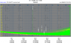
I got a chance to upgrade to the latest firmware and driver. They are both working fine. The attached image is a 6 average of a 16,777,216 point FFT. It takes about 20 minutes to run using Praxis which uses the Windows Audio system. That it works is a real testament to stability since a single dropped sample will totally degrade the measurement.
Attachments
The next chapter of the weird story.
First let me stress that with termination only with the resistor I get always the low noise floor. Weirdness enters only as soon I add the capacitor to the termination in parallel. Input setting always 0dBV.
I made a new cable. The new cable has a slightly different layout: The shield of the differential pair is connected to the shield terminal of the XLR connector (only). A separate ground wire is connected to pin 1, which is used to ground the terminator.
The old cable had the shield connected to pin 1 and used the decided ground terminal of the analyser. As shield and pin 1 are grounded on the analyser side, there is no topological difference (... well see the end of the story).
To reduce possible fault reasons, I soldered the cable and the ground connection directly on the the termination, so avoiding the RCA connector.
Green curve 620R termination, red 620R plus 1.5nF termination ... same picture as with the first cable.

Note that the higher noise floor looks like the noise floor with floating input, however the floating input noise floor (red) is slightly higher that the noise floor with 620R plus 1.5nF termination (green).

So far not much new ... but then I removed the metal housing of the XLR connector of the new cable and plugged it in the analyser to make some measurements on the contacts ... and by magic the noise floor (620R plus 1.5nF termination) dropped to the resistor only noise floor. There were more and higher line artefacts, but they disappeared when I connected the now floating shield to ground via the dedicated ground terminal.


This is twofold weird.
1. that the noise floor dropped.
2. that the noise floor did not raised again when I connected the shield to the dedicated ground terminal. The XLR input connector of the analyser has internally connected shield terminal and and pin 1 (ground).
The metal housing of the cable has good connection to analyser ground when plugged in.
When I measure the to-ground resistance with a meter (in 2-wire setup), I can not see any difference independent of the way of connection.
I could try a 4-wire resistance measurement but for that I would need to make some suitable probes.
First let me stress that with termination only with the resistor I get always the low noise floor. Weirdness enters only as soon I add the capacitor to the termination in parallel. Input setting always 0dBV.
I made a new cable. The new cable has a slightly different layout: The shield of the differential pair is connected to the shield terminal of the XLR connector (only). A separate ground wire is connected to pin 1, which is used to ground the terminator.
The old cable had the shield connected to pin 1 and used the decided ground terminal of the analyser. As shield and pin 1 are grounded on the analyser side, there is no topological difference (... well see the end of the story).
To reduce possible fault reasons, I soldered the cable and the ground connection directly on the the termination, so avoiding the RCA connector.
Green curve 620R termination, red 620R plus 1.5nF termination ... same picture as with the first cable.
Note that the higher noise floor looks like the noise floor with floating input, however the floating input noise floor (red) is slightly higher that the noise floor with 620R plus 1.5nF termination (green).
So far not much new ... but then I removed the metal housing of the XLR connector of the new cable and plugged it in the analyser to make some measurements on the contacts ... and by magic the noise floor (620R plus 1.5nF termination) dropped to the resistor only noise floor. There were more and higher line artefacts, but they disappeared when I connected the now floating shield to ground via the dedicated ground terminal.
This is twofold weird.
1. that the noise floor dropped.
2. that the noise floor did not raised again when I connected the shield to the dedicated ground terminal. The XLR input connector of the analyser has internally connected shield terminal and and pin 1 (ground).
The metal housing of the cable has good connection to analyser ground when plugged in.
When I measure the to-ground resistance with a meter (in 2-wire setup), I can not see any difference independent of the way of connection.
I could try a 4-wire resistance measurement but for that I would need to make some suitable probes.
This has all the indications oh nd oscillation. Do you have a wideband scope? Make a small pickup coil and hold it near the wiring to see the oscillation without affecting it. The low noise input circuit can become an oscillator when everything is "just perfectly wrong".
It could actually indicate something like that. I did have some instability on the prototype units, but I was convinced that I had solved it before the production run for the group buy. I have not seen it in my tests of these units, but perhaps a particular input termination can still provoke it?
Most likely some combination can. Low noise ditates low impedances in places where you would want high impedances to deal with oscillation. in particular the loop from the input and its associated grounds connecting to external cables.
What would help here is a photo of the cables and setup that are causing these issues. The fix may be as simple as a ferrite bead on each wire where they connect to the PCB. Unless the connectors are PCB mounted. . .
What would help here is a photo of the cables and setup that are causing these issues. The fix may be as simple as a ferrite bead on each wire where they connect to the PCB. Unless the connectors are PCB mounted. . .
I only have an analog scope (400MHz bandwidth), but if the oscillation is stable and more or less stable in frequency, I should see it. I will try to do the measurement with the coil.
I will also make some photos of cables and termination.
But the whole started by seeing that problem while measuring a real DUT, the DAM-DAC.
I will also make some photos of cables and termination.
But the whole started by seeing that problem while measuring a real DUT, the DAM-DAC.
With the suggested coil probe I found a signal correlated to the higher noise floor:

So the oscillation is of about 12.7MHz. There is some higher frequency component that is independent from the RTX-setting.
The displayed curve goes away if I go away with the probe from the termination. It goes also away if I remove the shield of the XLR connector (i.e. get the lower noise floor). I get a similar picture with the first cable.
Here a picture of the coil probe. It has an inductivity of about 0,4uH.

Here a picture of the termination of the cable.

And here the cable itself.

The cable with the balanced pair (white sleeve; twisted red,blue cable) is 18AWG (0.8qmm) wire as well as shield and has double isolation PTFE over Kapton. Red is to XLR-pin-2, blue to XLR-pin-3, shield to XLR-shield. The black ground cable (XLR-pin-3) is 16AWG (1.5qmm).
The length of the cable is about 80cm.
You get the best reading of the oscillation, when putting the coil right on the red and blue cables just before the termination.
The first cable was a microphone cable with an RCA connector on one side, thinner wires but shorter.
So the oscillation is of about 12.7MHz. There is some higher frequency component that is independent from the RTX-setting.
The displayed curve goes away if I go away with the probe from the termination. It goes also away if I remove the shield of the XLR connector (i.e. get the lower noise floor). I get a similar picture with the first cable.
Here a picture of the coil probe. It has an inductivity of about 0,4uH.
Here a picture of the termination of the cable.
And here the cable itself.
The cable with the balanced pair (white sleeve; twisted red,blue cable) is 18AWG (0.8qmm) wire as well as shield and has double isolation PTFE over Kapton. Red is to XLR-pin-2, blue to XLR-pin-3, shield to XLR-shield. The black ground cable (XLR-pin-3) is 16AWG (1.5qmm).
The length of the cable is about 80cm.
You get the best reading of the oscillation, when putting the coil right on the red and blue cables just before the termination.
The first cable was a microphone cable with an RCA connector on one side, thinner wires but shorter.
if you connect the low side to the shield through a 10 Ohm or 100 Ohm resistor does it still oscillate? Dose the frequency change a lot if you use a different style/construction cap? 12 MHz may be close to the self resonant frequency of the cap which combined with the low noise low Z connection could make the negative input into an oscillator. this is where the right ferrite bead can be magic.
@zfe = Very interesting tests, we keep for the next...
I am wondering about how will achieved the best sw support of RTX.
For this reason, I send an email to the info@artalabs.hr (ARTA) and ask them (Mateljan) if they are going to include the RTX to the next sw update.
I haven't any answer until now, but If someone knows the Mr Ivo Mateljan personally, I think it will be nice to ask him to support the RTX with ARTA, kindly.
Additionally, It will be nice to send similar email to the others team of fft software like AudioTester e.t.c for this purpose.
@zfe = Very interesting tests, we keep for the next...
I am wondering about how will achieved the best sw support of RTX.
For this reason, I send an email to the info@artalabs.hr (ARTA) and ask them (Mateljan) if they are going to include the RTX to the next sw update.
I haven't any answer until now, but If someone knows the Mr Ivo Mateljan personally, I think it will be nice to ask him to support the RTX with ARTA, kindly.
Additionally, It will be nice to send similar email to the others team of fft software like AudioTester e.t.c for this purpose.
As a software developer I would not understand a request "to support the RTX analyser". You'd be better of to give a specific description of the features you want, and how this would be useful to other/all users of the software.
It would also be useful if RTX would provide example source code of how to talk to the RTX to read and set the level switches. The interface description document is not easy to understand. A simple but complete code example would be much more useful.
- Home
- Design & Build
- Equipment & Tools
- DIY Audio Analyzer with AK5397/AK5394A and AK4490