Now to find the really lovely software interface.......
Let us know when you do
")
screens?
Ghianni, inserting an upright piece of aluminium cut from a can in the clips on the PCB between the input and output made a material difference to the cross coupling but of course that presume that the input is left open or at least sees a high impedance. Not a likely scenario for most real measurements but I have left the screen in place simply because its an easy 'fix' and isn't likely to compromise cooling. Didn't find adding screens in other locations had noticeable / any benefit including a crude version of the vertical screen shown in the prototype diagram you noted for a divider screen for the transformer area. Note my temp screens used mu-metal simply because I have some to hand so elec and magnetic screening was pretty good.
Ghianni, inserting an upright piece of aluminium cut from a can in the clips on the PCB between the input and output made a material difference to the cross coupling but of course that presume that the input is left open or at least sees a high impedance. Not a likely scenario for most real measurements but I have left the screen in place simply because its an easy 'fix' and isn't likely to compromise cooling. Didn't find adding screens in other locations had noticeable / any benefit including a crude version of the vertical screen shown in the prototype diagram you noted for a divider screen for the transformer area. Note my temp screens used mu-metal simply because I have some to hand so elec and magnetic screening was pretty good.
I recently noticed, in a waterfall spectrogram, two issues with low level peaks in the 80-90kHz area. Therefore I now had a closer look to that range. I did not notice this before as I mostly only displayed the audio range, moreover with Audiotester these are not drawn that readable as e.g. in Arta or in the spectrogram.
I will report that in two posts due to limitation of attachments.
Is that only with my RTX or a common problem ... and how do I get rid of it?
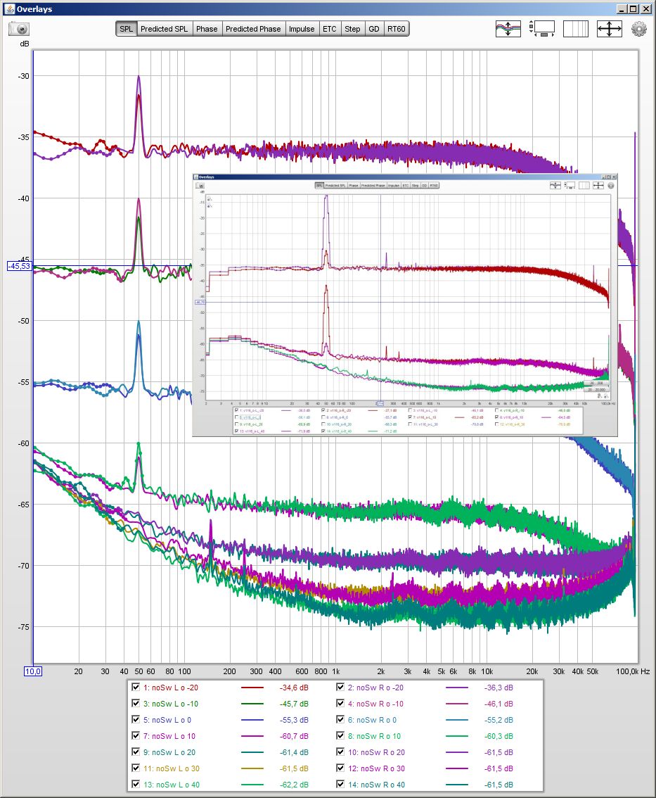
First issue, there is a -140dB peak around 87kHz that:
- appears only on the right channel
- only with input settings 40,30,20,10 dBV but not with 0, -10,-20 dbV.
- the relative "level" (FS) of the peak does not change with the input settings 40,30,20,10 dBV. So that indicates an problem after the input stage..??
Pictures:
First: right input shunted with 50R terminator, input settings 20,10,0dBV (peak, peak, no peak)


Second: left input shunted with 50R terminator, input settings 10dBv - no peak.

Third: right input balanced loopback to output, no signal playing, in is set to 10dBV and out set to 0dBV. The peak is there. The second peak at 94kHz comes from the output and is topic of my next post.

I will report that in two posts due to limitation of attachments.
Is that only with my RTX or a common problem ... and how do I get rid of it?
First issue, there is a -140dB peak around 87kHz that:
- appears only on the right channel
- only with input settings 40,30,20,10 dBV but not with 0, -10,-20 dbV.
- the relative "level" (FS) of the peak does not change with the input settings 40,30,20,10 dBV. So that indicates an problem after the input stage..??
Pictures:
First: right input shunted with 50R terminator, input settings 20,10,0dBV (peak, peak, no peak)
Second: left input shunted with 50R terminator, input settings 10dBv - no peak.
Third: right input balanced loopback to output, no signal playing, in is set to 10dBV and out set to 0dBV. The peak is there. The second peak at 94kHz comes from the output and is topic of my next post.
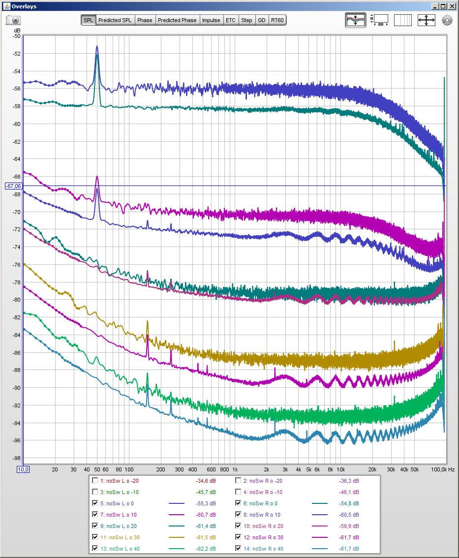
The second problem is(are) a "peak(s)" of the output. Here I have:
- similar behaviour on left and right channel
- the peak level changes according the output and input switch settings, so is something real at the output.
- the "peak" changes with the level of the played signal. The higher the played output signal is the pore the "peak" falls apart in lower frequency components an the "peak"-level drops.
Pictures: right channel, input usually set to 0dBV (so no issues from post 1 visible). Balanced connection.
First: output set to 0dbV from right to left: generator off, 1kHz played at -100,-60,-40,-20,-10dbV. The issue is the peak at around 94kHz that successively wanders left and falls apart.


Second: 1kHz Signal played at -100dBV (output 0dbV), input switch set to 0dbV, -20dbV, and left output with input switch 0dbV. We see for right the peak rises with higher amplification, as a real thing should. And left and right behave similar.


- similar behaviour on left and right channel
- the peak level changes according the output and input switch settings, so is something real at the output.
- the "peak" changes with the level of the played signal. The higher the played output signal is the pore the "peak" falls apart in lower frequency components an the "peak"-level drops.
Pictures: right channel, input usually set to 0dBV (so no issues from post 1 visible). Balanced connection.
First: output set to 0dbV from right to left: generator off, 1kHz played at -100,-60,-40,-20,-10dbV. The issue is the peak at around 94kHz that successively wanders left and falls apart.
Second: 1kHz Signal played at -100dBV (output 0dbV), input switch set to 0dbV, -20dbV, and left output with input switch 0dbV. We see for right the peak rises with higher amplification, as a real thing should. And left and right behave similar.
-140dB is in the parts per billion range if I have done my math right. So if that is the highest spur you observe you can claim an SFDR of 140dB which is rather good.
There are all sorts of mechanisms for capacitive coupling in switches, ICs, and the board itself, they will never be completely eliminated, and mitigating them is well beyond the point of diminishing returns.
The shielding that has been discussed seems like a good idea. I'd love to see a picture or two of that implemented as at some point I would likely want to do the same.
Yes -140dB is 0.1 ppb, but
for the input, if it is not on the left there is no reason to be on the right.
and for the output things are worse depending on the switch settings.
I have seen interesting effects of a DUT at -140dB level and would love if I not to have to worry each time if it is the analyzer or the DUT. After all I have bought the analyzer for its performance The old DACs/ADCs I have are not that much worse that I would not like to see unnecessary spikes be gone
for the input, if it is not on the left there is no reason to be on the right.
and for the output things are worse depending on the switch settings.
I have seen interesting effects of a DUT at -140dB level and would love if I not to have to worry each time if it is the analyzer or the DUT. After all I have bought the analyzer for its performance
The old DACs/ADCs I have are not that much worse that I would not like to see unnecessary spikes be gone Actually there is a reason for it to be on the right, although it may not be obvious at first sight.
If you look at the data sheet for the AK5394A page 22, a spurious noise of about -135 dBFS is mentioned for the left channel at no input. This is probably what you see here.
You may of course protest saying that you see it on the right channel. That is totally correct. The reason that you see it on the right channel is that the channels are swapped in the XMOS due to PCB layout given by the IC pin-out.
I could have crossed the audio lines on the PCB, but I chose to swap them in SW instead.
In principle the spurious could perhaps be moved outside the frequency band, but with a DC coupled input amplifier with several gain settings, and taking into account the temperature drift, I decided not to try to remove it. In reality it shouldn't really be a problem.
I protest forthat:
The last picture, first post, shows, that the peak is there with a -100dBFS signal (actually it is there up to -90dBFS).
Moreover it is there only for input switch settings of 10dBV and above (without changing the level). Did the additional little board not switch of the protection for these settings?
I agree it should be no problem as long one knows under which circumstances it appears and thus can be ignored.
By the way "the output peaks" get much severe in unbalanced operation. I will see to make a picture tomorrow and check if it was with the "good" cable.
I should be able to make the output peak visible on the scope if needed, I just would need to make the needed cables to connect first.
forthat:The last picture, first post, shows, that the peak is there with a -100dBFS signal (actually it is there up to -90dBFS).
Moreover it is there only for input switch settings of 10dBV and above (without changing the level). Did the additional little board not switch of the protection for these settings?
I agree it should be no problem as long one knows under which circumstances it appears and thus can be ignored.
By the way "the output peaks" get much severe in unbalanced operation. I will see to make a picture tomorrow and check if it was with the "good" cable.
I should be able to make the output peak visible on the scope if needed, I just would need to make the needed cables to connect first.
OK, I guess I had a case of information overflow
The peak at 87 kHz looks like the spurious from the ADC.
The other peaks are from the DAC.
If the DAC was for audio playback only, there would probably be a low pass filter, which would attenuate these peaks. But that cannot be done here, since the target is a flat frequency response all the way to 90 kHz.
I have been testing my USB DAC with RTX.
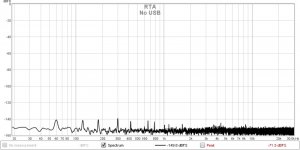
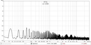
I see this strange noise at the output of my DAC only when its connected to the USB port of my laptop. Same issue even with another laptop. Just leaving the laptop on battery also doesnt make a difference.
Any advice on what the source of this noise could be?
The USB interface is an ExaU2I which has built in isolator.
Attachments
Last edited:
I have been testing my USB DAC with RTX.
I see this strange noise at the output of my DAC only when its connected to the USB port of my laptop. Same issue even with another laptop. Just leaving the laptop on battery also doesnt make a difference.
Any advice on what the source of this noise could be?
The USB interface is an ExaU2I which has built in isolator.
Does that noise change if you play some test signal through the USB/DAC?
Also, how is the USB interfaced to the DAC? For example, some USB-to-I2S converters output an I2S signal as soon as they are connected to USB. If the DAC chip has some internal processing of the I2S data stream, you may see the residual noise of this processing. For example, the DDDAC does this, I believe.
This is my GB for RTX6001 Audio Analyzer with AK5394A and AK4490 post #960 - hope this is a better place.
If I remember correctly, there is an amplifier involved below 20 dB - looks like this amp reacts on mains.
Much higher averaging reveals strange noise curves at the rigth channel:
Ulli
Originally Posted by zfe
Is the mains power now running through the whole case to the switch in front?
My device shows quite an impact of that cable to the mains switch:Originally Posted by JensH
Yes it is. So far I haven't noticed any drawbacks from this.
In case the cable to the front switch is not used, the picture changes (cf. first attached thumbnail)
inserted diagram shows what I got with power switch cable in use:
50 Hz peak is much higher at the left channel
without that cable both channels are almost identical - greatIf I remember correctly, there is an amplifier involved below 20 dB - looks like this amp reacts on mains.
would like to learn how to cure that
Much higher averaging reveals strange noise curves at the rigth channel:
would be great to have the right channel as smooth as the left one - any ideas?
Ulli
@Modmix = I think your problem will be solved with the appropriate shield in internal of RTX.
See, some tries that I have done at post 1865.
Now, I used a double cooper pcb (1.4mm thickness) at the same area, with very good results at hum and crosstalk!
Jens, has designed a shield for that reason, also...and soon this will be available as upgrade product.
See, some tries that I have done at post 1865.
Now, I used a double cooper pcb (1.4mm thickness) at the same area, with very good results at hum and crosstalk!
Jens, has designed a shield for that reason, also...and soon this will be available as upgrade product.
- Home
- Design & Build
- Equipment & Tools
- DIY Audio Analyzer with AK5397/AK5394A and AK4490