autoranging in action
This evening I finished a first (still a draft) implementation of a auto-ranging behaviour for the input and output attenuators of the RTX6001. Furthermore the results are directly scaled to "real world" voltages. Of course, manual control (with scaling) is still possible.")
Due to the lack of a apropriate voltage reference, I am relying on the factory calibration of the RTX6001 (for now). Comparing with my Keithly2015 it seems reasonable accurate.
Thanks to the excellent work of Jens and his colleaques this was only few lines of code away. This a very professional product with lots of applications throughout the (audio-)industry. Thank you so much!
I am working with Mathworks Matlab. Therefore, I am not really sure about the amount of interest people have into these kind of things...
This evening I finished a first (still a draft) implementation of a auto-ranging behaviour for the input and output attenuators of the RTX6001. Furthermore the results are directly scaled to "real world" voltages. Of course, manual control (with scaling) is still possible.
Due to the lack of a apropriate voltage reference, I am relying on the factory calibration of the RTX6001 (for now). Comparing with my Keithly2015 it seems reasonable accurate.
Thanks to the excellent work of Jens and his colleaques this was only few lines of code away. This a very professional product with lots of applications throughout the (audio-)industry. Thank you so much!
I am working with Mathworks Matlab. Therefore, I am not really sure about the amount of interest people have into these kind of things...
I had noticed that the left input channel has a little hum noise (50Hz) but at the right there is no any hum noise.
I decided to open the unit and make some measurements and tests about this.
I noticed that this 50Hz (hum) on the left channel is due to the proximity of the right generator to the left input.
At this area, there are some points for shielding.
Do you remember the nice shield that PaulBC has made? But, JensH had saind that there is warranty issue due temperature increase.
For this reason I did some measurements with not a closed shield but with a vertical pieces by aluminum double tape.

The hum of 50Hz will be decreased a lot of, if you put a piece of double aluminum tape between the right output and the left input.

If you set more of these tapes to the various places as the middle of the inputs and between the inputs and the ADC, the crosstalk at very low frequencies will be improved.


With that method, the temperature of this area not will increased and I think that there is no any warranty problem.
I decided to open the unit and make some measurements and tests about this.
I noticed that this 50Hz (hum) on the left channel is due to the proximity of the right generator to the left input.
At this area, there are some points for shielding.
Do you remember the nice shield that PaulBC has made? But, JensH had saind that there is warranty issue due temperature increase.
For this reason I did some measurements with not a closed shield but with a vertical pieces by aluminum double tape.
The hum of 50Hz will be decreased a lot of, if you put a piece of double aluminum tape between the right output and the left input.
If you set more of these tapes to the various places as the middle of the inputs and between the inputs and the ADC, the crosstalk at very low frequencies will be improved.
With that method, the temperature of this area not will increased and I think that there is no any warranty problem.
Last edited:
I have also put a metal shield in the clips between Rout/Lin.
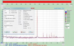
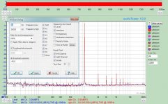
Now something else: Take a look a the pics below, same settings(-3.099dBFS, 44.1kHz, 32Bit, Window Rife-Vincent-3, average 5) the only differences are in the Analyze dialog window. Is this a bug of the SW?
Now something else: Take a look a the pics below, same settings(-3.099dBFS, 44.1kHz, 32Bit, Window Rife-Vincent-3, average 5) the only differences are in the Analyze dialog window. Is this a bug of the SW?
Attachments
Well, I'm not big into number crunching. Will your code work on some free version of Matlab?
-Chris
No. Basically, the connection to the RTX relies on the HIDAPI which was also mentioned before. But the internal processing, especially the realtime audio in/out, is conducted via proprietary Matlab.
Personally, I do not like it the proprietary way, but It gets the Job done fast and efficient. The latter is currently more important to me. Because, rather than programming stupid software-tools in my spare time, I'd prefer finishing some of the amplifier and loudspeaker projects I have started (and never finished) over the recent years.
I did some experiments on the aliasing of the ADC.
The data sheet of the AK5394 says it does 128-times oversampling and has a digital low pass filter for suppressing the aliasing.
Thus for fs=48kHz sampling frequency the ADC samples internally with 6,144MHz.
Summery of the Measurements:
1. The signal level starts to drop slightly before fs/2 and we see some aliasing artifacts for frequencies slightly above fs/2 but vanishing fast.
2. For signals of about 6,144MHz we are with the aliases again in the passband of the filter and see noticeable peaks. However they are about 60dB weaker than the signal, probably due to the fact that the input stage is not meant for this frequencies.
3. For fs=192kHz we see also the first artefacts again for signals of about 6,144MHz. Thus, not surprisingly, the ADC samples always internally with 6,144MHz, only the oversampling rate drops with increasing fs.
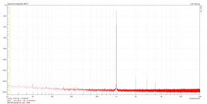
Some pictures. The RTX 6001 input was set to 10dBV the function generator (a vintage HP8116A - thus do not expect too good signal quality) was set to 1VRMS output.
First fs=48kHz, signal roughly 23,5kHz, 24kHz,25kHz, 26kHz, 6,2Mhz (fist to last picture).


For fs=192kHz, signal roughly 93kHz, 95kHz, 97kHz, 101kHz, 6,1MHz.


The data sheet of the AK5394 says it does 128-times oversampling and has a digital low pass filter for suppressing the aliasing.
Thus for fs=48kHz sampling frequency the ADC samples internally with 6,144MHz.
Summery of the Measurements:
1. The signal level starts to drop slightly before fs/2 and we see some aliasing artifacts for frequencies slightly above fs/2 but vanishing fast.
2. For signals of about 6,144MHz we are with the aliases again in the passband of the filter and see noticeable peaks. However they are about 60dB weaker than the signal, probably due to the fact that the input stage is not meant for this frequencies.
3. For fs=192kHz we see also the first artefacts again for signals of about 6,144MHz. Thus, not surprisingly, the ADC samples always internally with 6,144MHz, only the oversampling rate drops with increasing fs.
Some pictures. The RTX 6001 input was set to 10dBV the function generator (a vintage HP8116A - thus do not expect too good signal quality) was set to 1VRMS output.
First fs=48kHz, signal roughly 23,5kHz, 24kHz,25kHz, 26kHz, 6,2Mhz (fist to last picture).
For fs=192kHz, signal roughly 93kHz, 95kHz, 97kHz, 101kHz, 6,1MHz.
@ Jens:
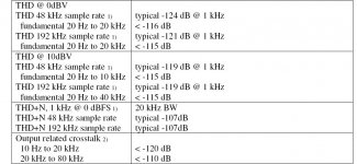
On the specification page of the RTX6001 unit there were mentioned figures of THD, THD+N, seen on the attached jpg. I assume that these measurements have been taken using audio-Tester V3. Would you please define the full setup applied to the SW and the unit of receiving these results?
On the specification page of the RTX6001 unit there were mentioned figures of THD, THD+N, seen on the attached jpg. I assume that these measurements have been taken using audio-Tester V3. Would you please define the full setup applied to the SW and the unit of receiving these results?
Attachments
Last edited:
RTX6001 Manual Ranging
RTX6001 Manual Ranging (for audio Tester V3)
For those that want real world volts or dBV values that scale to real world Vrms.
Select the input switch position with full scale Volts nearest to but larger than your DUT output voltage. Go into the options selection “calibration” and input and enter the full scale volts in millivolts and enter. The FFT will be scaled in real world volts.
For switch position 1; full scale input equals 100Vrms = 100000mv
For switch position 2; full scale input equals 31.6Vrms = 31600mv
For switch position 3; full scale input equals 10Vrms = 10000mv
For switch position 4; full scale input equals 3.16Vrms = 3160mv
For switch position 5; full scale input equals 1.00Vrms = 1000mv
For switch position 6; full scale input equals 0.316Vrms = 316mv
For switch position 7; full scale input equals 0.100Vrms = 1000mv
To set the generator output voltage you need to calculate the dBFS value to enter in the output setting menu.
The maximum output voltage for Switch
#1 = 100mv
#2 = 1V
#3 =10V
For switch position number 1; dBFS = 20 * Log(Desired volts) + 20 . Switch #1 max Volts = 0.1 .
For switch position number 2; dBFS = 20 * Log(Desired volts) . Switch #2 max Volts = 1 .
For switch position number 3; dBFS = 20 * Log(Desired volts) - 20. Switch #3 max Volts = 10 .
DT
Last edited:
0.1vrms would be 100mv
Thank you, you are so correct.
For switch position 7; full scale input equals 0.100Vrms = 100mv
I perseverated on the keyboard.
DT
The maximum output voltage for Switch
#1 = 100mv
#2 = 1V
#3 =10V
Just to avoid confusion, these are sine-RMS values, NOT maximum voltages. The max would be approx. 141 mv, 1.41 V, and 14.1 V.
Congratulations! At least one is very interestedThis evening I finished a first (still a draft) implementation of a auto-ranging behaviour for the input and output attenuators of the RTX6001. [...]
I am working with Mathworks Matlab. Therefore, I am not really sure about the amount of interest people have into these kind of things...
. Would you mind sharing? I use Mac OS X and unless you do too, will need to build a mex file on a Mac. Maybe this should go to a new thread unless Jens prefers to keep RTX HID-related discussion here? In any case, thanks to Jens, Mat and you!edit: Since GNU Octane also can build mex files, I suspect your HIDAPI code should be compatible with MATAA.
Last edited:
Hello,
I recall seeing an old Popular Mechanics Magazine with a telephone dial on the front cover. I think 1959. The telephone dial was the input device to an early DIY computer. To enter data the numbers needed to be converted to binary zeros and ones. When the computer was finished crunching, the output needed to be converted back into 10 base by the user.
This is much the way I see inputting voltages into the RTX6001. There is room to progress.
One place to start the progression is the RTX6001 Attenuation Control Program.
Looking at the audio Tester user manual, aT V3 uses a .INI file, a Configuration file to handle and keep configuration and calibration information. This .INI file configuration and calibration information is loaded each time audio Tester is booted and can also be updated on the fly while the program is in use.
I can picture new graphic windows in the RTX6001 Attenuation Control Program. There could be a check box for balanced input and another check box for unbalanced input. Then there could be check boxes for input and output selector switch positions. You could directly enter desired output voltages. All the dBFS scaling would happen out of sight and out of mind.
This is all an introverts’ day dream.
DT
Last edited:
@ Jens:
On the specification page of the RTX6001 unit there were mentioned figures of THD, THD+N, seen on the attached jpg. I assume that these measurements have been taken using audio-Tester V3. Would you please define the full setup applied to the SW and the unit of receiving these results?
This technical section has measurements at two levels, 0/10dBV at 48K@1KHz but there is no any information about the signal level of gen, the FFT resolution, the Window e.t.c.
With a well pre-warm unit, I could to catch the specification only at 10dBV, 48KHz@1KHz but with -10dBFS signal gen (131K, Kaizer7) with ARTA. Almost 0.000089% at the left or right channel (mono).
This meaning that a level of -121dB has achieved vs -119dB of typical.
I had the same level of -121dB and with 0dBV (the rest same like before), I was -3dB under from the -124dB of typical.
Attachments
I can picture new graphic windows in the RTX6001 Attenuation Control Program. There could be a check box for balanced input and another check box for unbalanced input. Then there could be check boxes for input and output selector switch positions. You could directly enter desired output voltages. All the dBFS scaling would happen out of sight and out of mind.
I don't know audioTester, but what you describe is already possible with MATAA. While there are no pretty windows and checkboxes, the user can specifiy the signal voltage and a calibration file (that corresponds to the current level settings) for each measurement. I am sure similar things are possible with other software, too.
Congratulations! At least one is very interested
edit: Since GNU Octane also can build mex files, I suspect your HIDAPI code should be compatible with MATAA.
If I am going to add functionality to control the RTX level switches from within MATAA, I want it to work on Mac, Windows and Linux, and on both Octave and Matlab. While it might be possible to use Black_Chicken's solution with MATAA on Matlab, it does not work on Octave (Black_Chicken provided some test files for me to try, so I know it does not work on Octave). However, while I do have ideas of how this could be solved, I have to say that the current way of working with predefined calibration files for the different level settings works fine for me, so this is not an urgent issue for me.
I don't know if I have understood well, but this limitation with calibration at each attenuate position, there isn't on ARTA.
If you calibrate an -3dBFS input signal at one position e.g 0dBV, the signal threshold at the bottom will indicated -3dBFS.
If you continue change the attenuate position e.g to 10dBV, the signal threshold at the bottom will indicated -13dBFS and so on upper or down.
From this, I can conclude that there is no need of calibration to each attenuate position on ARTA but only to one.
Am I right? Is that the talking point about?
If you only display the vertical scale in dBFS, there is no need to calibrate at all, dBFS is by definition relative.
Calibration is required, when you display the vertical scale in dBV (or dBU, ... etc.), and a different calibration value is required for each attenuate position, or else you'll get wrong values.
Calibration is required, when you display the vertical scale in dBV (or dBU, ... etc.), and a different calibration value is required for each attenuate position, or else you'll get wrong values.
- Home
- Design & Build
- Equipment & Tools
- DIY Audio Analyzer with AK5397/AK5394A and AK4490