I have made the following two observations and would like to know if this is "normal"?
1.) The noise floor of the output set to 20dBV is much higher than for 0dBV or -20 dBV. In the later cases a loopback measurement (no signal playing) looks alike as the measurement with the input shunted with a 50 Ohm termination.
2.) If I play a 1kHz signal in loopback mode to one channel I see the signal and its harmonics weak also on the other input channel although I have this input shunted with a 50 Ohm termination.
Some pictures. The settings are: sample rate 192kHz, the inputs are set to 10dbU.
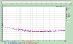
First picture; No signal playing, output set to 0dBV, right channel in loopback, left input shunted with a 50 Ohm termination.

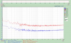
Second picture; No signal playing, output set to 20dBV, right channel in loopback, left input shunted with a 50 Ohm termination.

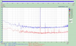
Third picture; 1kHz signal at -20dBFs is playing, output set to 20dBV, left channel in loopback, right input shunted with a 50 Ohm termination.

1.) The noise floor of the output set to 20dBV is much higher than for 0dBV or -20 dBV. In the later cases a loopback measurement (no signal playing) looks alike as the measurement with the input shunted with a 50 Ohm termination.
2.) If I play a 1kHz signal in loopback mode to one channel I see the signal and its harmonics weak also on the other input channel although I have this input shunted with a 50 Ohm termination.
Some pictures. The settings are: sample rate 192kHz, the inputs are set to 10dbU.
First picture; No signal playing, output set to 0dBV, right channel in loopback, left input shunted with a 50 Ohm termination.

Second picture; No signal playing, output set to 20dBV, right channel in loopback, left input shunted with a 50 Ohm termination.

Third picture; 1kHz signal at -20dBFs is playing, output set to 20dBV, left channel in loopback, right input shunted with a 50 Ohm termination.

I have seen similar effects, but not as strong. With MATAA, the noise floor was a wee bit higher with the 10V output than with the 1V output (mainly at low frequencies). With REW, it was the other way round. See attached files.
I have no clue what's going on, or what REW does with the data. I decided that the differences are not big enough for me to worry. Yours seem to be more substantial, though.
I have no clue what's going on, or what REW does with the data. I decided that the differences are not big enough for me to worry. Yours seem to be more substantial, though.
Attachments
I tried an single ended connection. There is a lot of 50Hz and harmonics as soon as I plug in the XLR-to-BNC adapter to the ADC input (independently if I connect it with a cable to the BNC out of the DAC).
It is here an old building with old electrical installation perhaps one reason ... I'll try at night again with as much other devices plugged off.
The attached picture: Input set to 10dBV, output to 0dBV left in-and output connected by a BNC cable, no signal. Right input shunted with a 50 Ohm termination.

Single ended input requires correct cable arrangement ( mentioned earlier) Pin 1 on the XLR input connection as well as Source side earth/shield connection have impact on the noise. I tried HP 239A oscillator with RTX and Pin 1 should be disconnected for low noise on the ADC.
Attachments
This capture is using smoothing to remove the grass at the lower end - to see harmonic content clearly
I used a Neutrik BNC XLR adapter (XLR Pin 1 and 3 connected). As I said source or no source makes not much difference.
Yes, that looks fairly normal.I have made the following two observations and would like to know if this is "normal"? <snip>
1) The DAC + filter + buffer always work at the full signal level. This is then followed by a passive attenuator to keep the noise at a low level when testing equipment, which work at low input levels.
When you set the output to 20 dBV the noise from the DAC + filter + buffer (mainly the DAC) will pass through to the output directly.
When you set the output to 0 dBV the noise from the DAC + filter + buffers will be attenuated by 20 dB. So the total noise will be this attenuated noise + a small amount of thermal noise from the output attenuator (50 ohm).
And the input noise will add to the output noise.
With the output at -20 dBV the nosie from the DAC + filter + buffer will be attenuated by 40 dB.
2) This looks like crosstalk. There will be some crosstalk coupled into the input amplifier and there will be some crosstalk in the ADC chip. I haven't checked whether the exact levels are typical. You haven't described what the input attenuator setting was.
I used a Neutrik BNC XLR adapter (XLR Pin 1 and 3 connected). As I said source or no source makes not much difference.
You should probably try circuit no. 17 from this:
Sound System Interconnection
If you have e.g. an amplifier connected, remember to connect the ground of the amplifier to the ground of the analyzer. This may already be connected if you use the analyzer also as the source.
I suspect also RTX power cable earthing ? Check whether your house earthing proper and you are using 3 pronged power plug. I had seen such spike when even the source is connected to 2 pin power supply socket. RTX is so sensitive, earth connection is important
and the units are built correctly.
too many poorly (incorrectly) grounded pieces out there. See "pin 1 problem"
Alan
too many poorly (incorrectly) grounded pieces out there. See "pin 1 problem"
Alan
Here are a few spectrum analysis plots I made with MATAA today.
The first two plots show loopback tests with different bit depth settings on the Mac (in Audio MIDI program). The first is 24 bit, the second is 16 bit. This shows that it's important to get the bit-depth settings right (24 bit is required to get the full dynamic range).
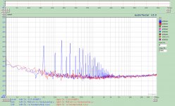
The third plot shows the spectrum of my old Pioneer A-445 integrated amplifier, using an XLR-to-RCA converter on the RTX output. The POS and NEG pins of the balanced RTX input were connected to the dummy load on the amplifier output to probe the amplifier output. The chassis pin of the RTX input was not connected to anything. The amp has a two-prong mains cable, so I guess the only earth connection is through the RTX chassis + mains cable. Is there a way to improve the mains noise in this measurement (peaks at 50 Hz, 100 Hz, etc.)?
Attachments
Have you tried using the BNC output instead of XLR + converter?
Have you tried to connect the chassis of the amplifier and the analyzer?
What is the hum level of the amplifier itself? Is this test setup wiring related or related to the amp itself?
Have you tried to connect the chassis of the amplifier and the analyzer?
What is the hum level of the amplifier itself? Is this test setup wiring related or related to the amp itself?
Have you tried using the BNC output instead of XLR + converter?
Yes, didn't make a difference (I used a BNC-to-RCA converter on the RTX's BNC, so the BNC shield / RTX chassis was connected to the RCA-GND -- is this ok?)
Have you tried to connect the chassis of the amplifier and the analyzer?
Yes, didn't make a difference.
What is the hum level of the amplifier itself? Is this test setup wiring related or related to the amp itself?
The hum goes down quite a bit if I leave the amp input shortened (and disconnected from the RTX output).
Hello,
Just an idea mbrennwa, maybe as suggested by JensH, the noise hum at line frequency could coming from the amplifier itself ?
If i suppose you test a linear amplifier powered by linear PSU (transformer+rectifier+caps filtering),
so when you start to deliver some power at output there is a ripple (mainly at 2x line freq) that appear on power rail of your power amplifier board.
So , the power supply rejection (PSSR) of the amplifier is not perfect and then some of these disturbances can be seen on the output spectrum.
That explain also why with your amplifier input shorted (no output power), there is no line harmonics on spectrum(no ripple on supply rails).
To verify the hypothesis, you could try at fixed output voltage of the amplifier to increase the output current (lower load value)
and then see if the line harmonics levels goes up.
(The ripple on supply rails will increase if output power increase).
Regards.
Frex
10dBVYou haven't described what the input attenuator setting was.
You should probably try circuit no. 17 from this:
Sound System Interconnection
If you have e.g. an amplifier connected, remember to connect the ground of the amplifier to the ground of the analyzer. This may already be connected if you use the analyzer also as the source.
In the case here - a loopback measurement of the RTX6001 itself - the no-17 connection makes no difference as the sleeve of the BNC-out is connected to ground. It makes essentially no difference where I connect Pin 1 and 3 - at source side, at ADC side, or just connecting them and leave the 2-pin floating - I see the same.
I attached pictures for all input settings from 40dBV to -20dBV and, to compare, the last one the same (channels reversed) with a RME Fireface800 with -10dBV input stting.
The 50Hz related stuff is much less.
(P.S. the Fireface 800 manual tells you that you get 0 dBFS @ -10 dBV setting for +2 dBV - whatever the logic behind that is. So it compares to the RTX at 0dBV)
Attachments
Last edited:
Thanks! After I set both output and input to 24bit or 32bit the noise floor went down to where everyone else has it. Seems like the Audio Midi settings need manual updating every time one changes the device, sample rate or bit depth in the analyser software. Urgh.
For Mac:
To my experience you need the Audio Midi switching only with REW or ARTA/Audiotester running via WINE.
My audio-player software switches the sample rates of the RTX6001 fine itself (you see that at the entry at Audio Midi and hear the RTX clicking).
So it is not a genuine Mac problem, more one of the WINE-emulator or the Java-thing.
@JensH
A sample rate and bit depth indicator on a future Version of the RTX6001 would help to avoid pit falls more easily here.
- Home
- Design & Build
- Equipment & Tools
- DIY Audio Analyzer with AK5397/AK5394A and AK4490


