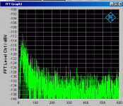
I am using a R&S UPV audio analyser to do measurements on a 120mA power supply. I can do reliable measurements down to about -144dBV but from there on I struggle with 50Hz and components that somehow seems to randomly appear (Norway). It can vary from -152dBV to -140dBV.
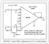
I have tried many things with grounding, shielding, and even built a INA103 +40dB front end but it did not help me very much.
Does anyone have a paper they can recommend? Or if someone want to help me I can elaborate a little more on my setup.
Armand
I have tried many things with grounding, shielding, and even built a INA103 +40dB front end but it did not help me very much.
Does anyone have a paper they can recommend? Or if someone want to help me I can elaborate a little more on my setup.
Armand
Armand,
Your doing well, I have components about -125dBV to -135dBV with my R&S UPD.
I'm not sure about the UPV, but on my UPD I can play with the analysers input Ground settings / floating or not... have you tried a thick ground strap from the earth terminals on the UPV to the DUT?
As your concerned about 50Hz and its harmonics - these are H-Field (magnetic) components and are very hard to shield.
A Balanced connection to the analysers is your friend here....
Thank you for your input John.
As a matter of fact I have had great progress tonight.
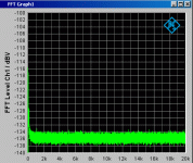
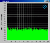
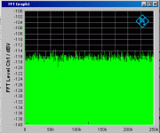
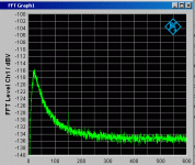
I now have the 50Hz at less than -160dBV as it has disappeared into the noise floor of my INA103 +40dB preamplifier. From the averaged measurements the noise floor sits at an amazing -175dBV above 250Hz. That is about 2nV rms!! With no averaging I have peaks at -165dBV above 250Hz.
That is really incredible results!
You were spot on when mentioning the ground strap between the DUT and the UPV. I used only a cheap thin wired crocodile clip connection but that eliminated 50Hz and components totally. (I did in fact try that before I read your reply and it bugs be a little now as I cannot really take credit for that myself anymore. haha )
)
If you are interested I am happy to describe in detail my triple shielding, grounding scheme and INA103 hookup. I am pretty green at this low level measurements so maybe you can help me with further improvements?
Attached is five measurements from tonight. Remember to subtract 40dB from the readings because of the +40dB preamplifier.
Also, I am using the 22Hz highpass filter on the UPV.
All measurements are using 256k FFT.
As a matter of fact I have had great progress tonight.
I now have the 50Hz at less than -160dBV as it has disappeared into the noise floor of my INA103 +40dB preamplifier. From the averaged measurements the noise floor sits at an amazing -175dBV above 250Hz. That is about 2nV rms!! With no averaging I have peaks at -165dBV above 250Hz.
That is really incredible results!
You were spot on when mentioning the ground strap between the DUT and the UPV. I used only a cheap thin wired crocodile clip connection but that eliminated 50Hz and components totally. (I did in fact try that before I read your reply and it bugs be a little now as I cannot really take credit for that myself anymore. haha
If you are interested I am happy to describe in detail my triple shielding, grounding scheme and INA103 hookup. I am pretty green at this low level measurements so maybe you can help me with further improvements?
Attached is five measurements from tonight. Remember to subtract 40dB from the readings because of the +40dB preamplifier.
Also, I am using the 22Hz highpass filter on the UPV.
All measurements are using 256k FFT.
Attachments
Armand,
Yes the R&S units are stunning - here's an example measurement with my UPD of a prototype DAC reproducing a 1KHz -150dB test tone!!!
Note the "Typical" 50Hz related residuals (also around -150dB).
Heres the DAC reproducing a -60dB test tone with the measured dynamic range of -132dB!
Here is a 1.2V regulator I designed for a new DAC I'm working on - note UPD's typical "Single End" 50Hz related components, I've not spent much time trying to reduce them - a ground strap would help
Yes the R&S units are stunning - here's an example measurement with my UPD of a prototype DAC reproducing a 1KHz -150dB test tone!!!
An externally hosted image should be here but it was not working when we last tested it.
Note the "Typical" 50Hz related residuals (also around -150dB).
Heres the DAC reproducing a -60dB test tone with the measured dynamic range of -132dB!
An externally hosted image should be here but it was not working when we last tested it.
Here is a 1.2V regulator I designed for a new DAC I'm working on - note UPD's typical "Single End" 50Hz related components, I've not spent much time trying to reduce them - a ground strap would help
An externally hosted image should be here but it was not working when we last tested it.
Last edited:
That is som really nice measurements you have there. I notice you are using dBr in your Y-axis. Is that because you are using a signal amplifier before the UPD?
The peaking I have around 30Hz is noise from the INA103. The FFT is identical with shorted inputs to the INA103. Yes, this is for an audio application. I am working on improving the PSU for a discrete preamp running class A. I might have a run at trying something else than the INA103 to have better noise floor below 300Hz.
The peaking I have around 30Hz is noise from the INA103. The FFT is identical with shorted inputs to the INA103. Yes, this is for an audio application. I am working on improving the PSU for a discrete preamp running class A. I might have a run at trying something else than the INA103 to have better noise floor below 300Hz.
Measurement setup
RNMarsh,
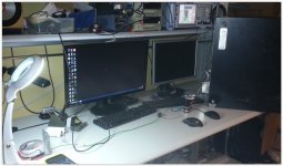
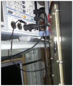
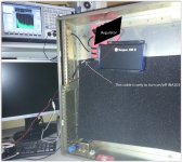
I did a drawing of my setup and took some pictures.
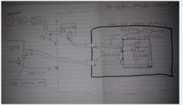
* Transformer about 1 meter away from measurement cabinet (BIG black)
* PI filter is outside the measurement cabinet to have least possible AC inside
* negative is connected with crocodile clip in its way into the measurement cabinet
* Inside the measurement cabinet sits the regulator to be tested (DUT)
* Output from regulator is connected to +40dB gain amplifier with antenna cable. Its the box that says "Seapos 100E". (An old GPS unit)
* negative is also connected to chassi of that box through the shield og the antenna cable
* inside the GPS box there is a smaller 3x4x5 cm box made of 1mm copperplate. The antenna cables shield (ground) is soldered to chassi of that copper box. Inside that copper box is the INA103 amplifier. Also inside the GPS box there are 2 11V Li-Po batteries that power the INA103.
* The INA103 uses 2x1uF polyprop capacitors and 20k resistors and a 20k pot to adjust offset. This gives a high pass filter with maxumum 0,2 dB error at 50Hz. (depending of pot setting). One of the INA103 inputs are soldered to the copper box together with antenna shield.
* The output signal from the INA103 is connected to pin 2 on the XLR input of the UPV instrument.
* Antenna shield is connected to XLR pin 1 and 3.
* The real trick here is to connect the big measurement box to chassi ground on the UPV instrument.
* The UPV instrument must be configured to have the XLR input floating to avoid 50Hz and components
I am sure there are alternative ways of hooking up the grounding, but this setup works really well.
View attachment 481135
RNMarsh,
I did a drawing of my setup and took some pictures.

* Transformer about 1 meter away from measurement cabinet (BIG black)
* PI filter is outside the measurement cabinet to have least possible AC inside
* negative is connected with crocodile clip in its way into the measurement cabinet
* Inside the measurement cabinet sits the regulator to be tested (DUT)
* Output from regulator is connected to +40dB gain amplifier with antenna cable. Its the box that says "Seapos 100E". (An old GPS unit)
* negative is also connected to chassi of that box through the shield og the antenna cable
* inside the GPS box there is a smaller 3x4x5 cm box made of 1mm copperplate. The antenna cables shield (ground) is soldered to chassi of that copper box. Inside that copper box is the INA103 amplifier. Also inside the GPS box there are 2 11V Li-Po batteries that power the INA103.
* The INA103 uses 2x1uF polyprop capacitors and 20k resistors and a 20k pot to adjust offset. This gives a high pass filter with maxumum 0,2 dB error at 50Hz. (depending of pot setting). One of the INA103 inputs are soldered to the copper box together with antenna shield.
* The output signal from the INA103 is connected to pin 2 on the XLR input of the UPV instrument.
* Antenna shield is connected to XLR pin 1 and 3.
* The real trick here is to connect the big measurement box to chassi ground on the UPV instrument.
* The UPV instrument must be configured to have the XLR input floating to avoid 50Hz and components
I am sure there are alternative ways of hooking up the grounding, but this setup works really well.

View attachment 481135


Last edited:
That is som really nice measurements you have there. I notice you are using dBr in your Y-axis. Is that because you are using a signal amplifier before the UPD?
I've never bothered with an additional gain stage in front of the UPD, my measurements are always "direct".
I always scale my measurements, E.g if measuring a 1.2V PSU the I set my reference at 1.2V, hence the dBr.
For the DAC then Full scale (0dB) 2Vrms or what ever the DAC's 0dB FS output level is (using the UPD's "Store" 0dBr option).
- Status
- This old topic is closed. If you want to reopen this topic, contact a moderator using the "Report Post" button.
- Home
- Design & Build
- Equipment & Tools
- Sub -140dBV measurements R&S UPV
